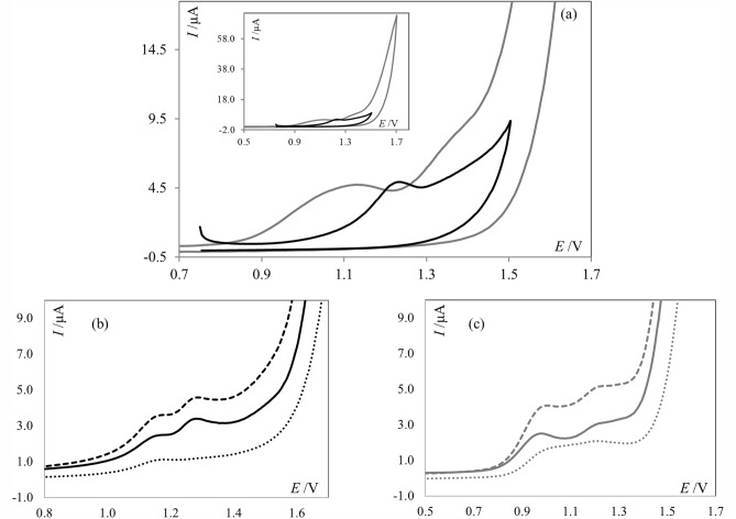
Figure 4.
(a) Cyclic voltammograms of PNT (1.0 × 10⁻⁴ mol L−1), obtained at scan rate of 50 mV s−1, black line represents the voltammograms recorded in acetate buffer of pH 4.7, gray line in PBS of pH 7.4. Inset: Represents the same voltammograms but in the wider potential range; (b) SW voltammograms of PNT (1.0 × 10⁻⁵ mol L−1, net current—solid line) and the forward (dashed line) and backward (dotted line) components of PNT signals recorded in acetate buffer of pH 4.7; (c) SW voltammograms of PNT (1.0 × 10⁻⁵ mol L−1, net current—solid line) and the forward (dashed line) and backward (dotted line) components of PNT signals recorded in PBS of pH 7.4.

