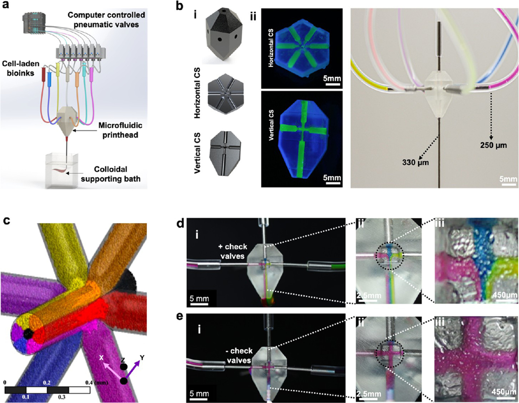
Figure 1.
M3 bioprinter and characterization of the fluid flow of bioinks in the printhead. (a) Schematic of the M3 bioprinting system showing major components in the form of computer-controlled WAGO system pneumatic valves, microfluidic single nozzle printhead, and colloidal gel support bath where inks extrude and cross-link in the form of 3D bioprints. (b-i) Computer-aided design (CAD) of the printhead showing horizontal and vertical sections, (b-ii) an actual printhead, and (b-iii) an assembly showing the connected single nozzle seven-ink printhead. (c) Flow simulation of seven inks. Six of the bioinks enter the printhead from the sides, with a seventh ink coming from an out-of-the-plane inlet and all the inks extrude from a single outlet nozzle. (d, e) Cross-sectional view of the printhead to confirm the effect of flow patterns of three inks (red, blue, green) on the backflow and intermixing of different bioinks in (d i–iii), the presence and (e i–iii), absence of check valves.

