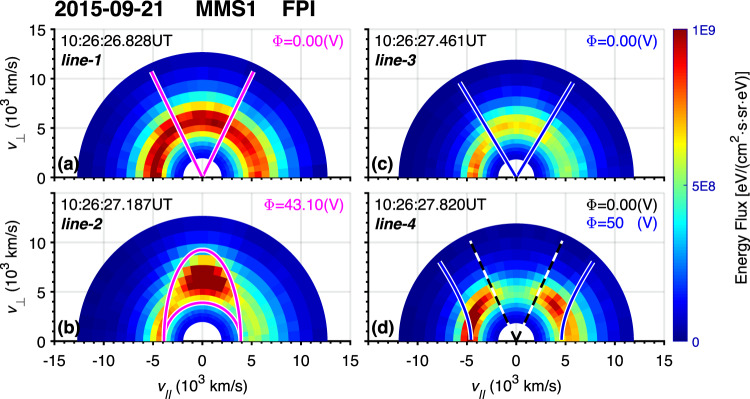
Fig. 2. Electron energy fluxes in v∥–v⊥ coordinates.
For all panels, the x- and y-axis are for v∥ and v⊥, respectively. In each panel, the universal time is labeled in the top left corner corresponding to one of the four vertical dashed lines in Fig. 2, and the assumed electric potential is labeled in the top right corner. The magenta line in panel (a) is the critical trapping angle given by Eq. (6). In panel b; there is an additional magenta line (the semicircle) representing the cut-off kinetic energy limit . The blue line in panel (c) is simply 60° and 120° pitch angle, the region between which is regarded as the source of the electron jet after line-3. The dashed black line in panel d illustrates the pitch angle limit due to purely mirror force (i.e., Eq. (4)). The blue line in panel d illustrates the critical trapping angle given by Eq. (6).

