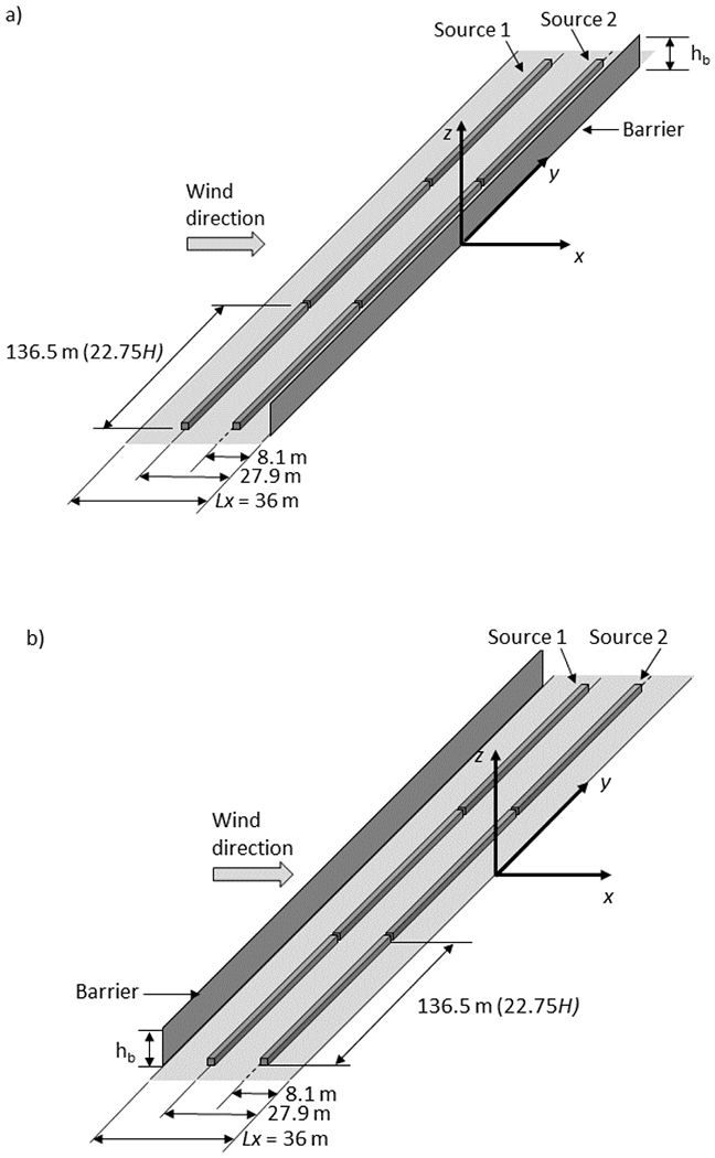
Fig. 1.

Wind tunnel setup showing the full-scale dimensions of two fixed line sources and a solid barrier, which are all perpendicular to the x-axis. The model scale is 1:150. Wind flows in the positive x direction. The origin is located at the downwind edge of the roadway; the y-axis is aligned with the downwind edge of the roadway. The No Barrier case uses this same setup but without a barrier present. a) The Downwind Barrier cases have a barrier located at x/H = 0. b) The Upwind Barrier cases have a barrier located at the upwind edge of the roadway (x/H = −6). Adapted from Francisco et al. (2022)
