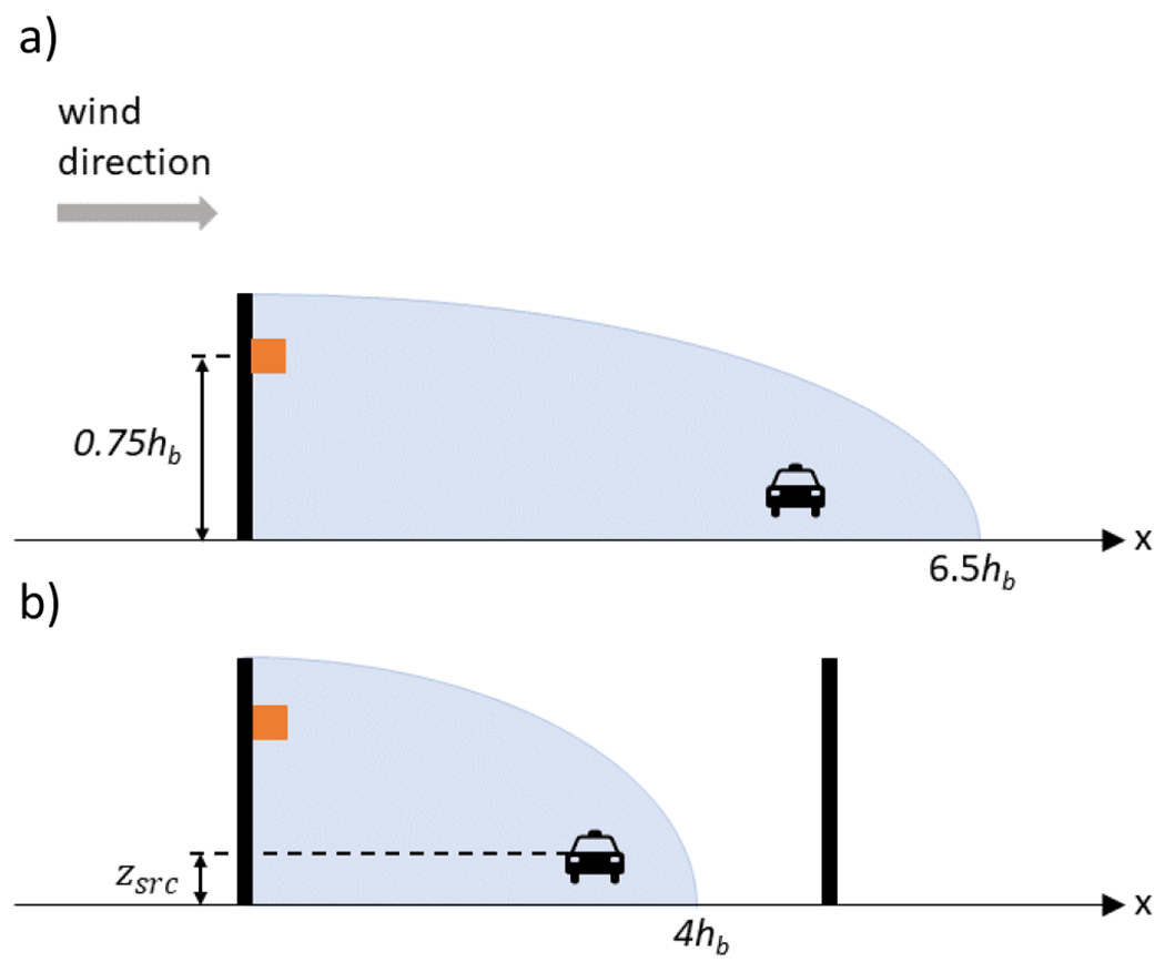
Fig. 5.

Diagram showing the proposed recirculation region (shaded region) for a one-barrier case (top) and a two-barrier case (bottom). The recirculation region extends from the upwind barrier location (black bar) to a downwind distance of a) 6.5 hb for the one-barrier case and b) 4 hb for the two-barrier case. For both cases, the original source height (car icon) is denoted as zsrc. If the original source is within the recirculation region, the source is moved to the location of the upwind barrier and to a source height of 0.75hb (orange square)
