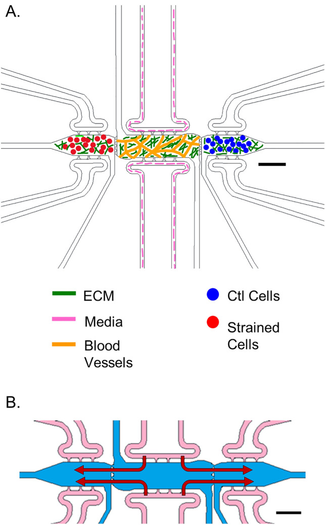
Figure 1.

Schematic of 3D multi-microtissue model experimental setup and flow conditions. (A) Illustration of typical setup for experiments, showing the 3 microtissues or chamber regions connected in parallel within a microfluidic device. The middle chamber was loaded such that a vascular network of self-assembled HMECs. Side microtissues were loaded with control (non-strained) or strained EOC cells. Each microtissue can be loaded independently, allowing for control over cell spatial orientation. Fluidic lines (top and bottom) allow for control over feeding of cells and diffusion between microtissues. (B) Flow pattern for the 3D TME experiments whereby media enters the device through the fluidic lines (pink) attached to the middle chamber (blue) and moves outward to the side chambers (red arrows). Scale bars = 500 μm Note—While all chambers have independent fluidic lines, only the media lines for the center chamber were utilized in this study. For more information on flow patterns in this model, see Ref. #49. Portions of this figure were previously published.
Reproduced from Ref. 49 with permission from the Royal Society of Chemistry.
