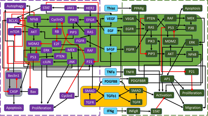
Figure 4: Wild-type PC wiring diagram with modules.
Shown are the highlighted modules (yellow, green, and grey) for the wild-type PC model in Figure 10, adapted from [1]. Black barbed arrows indicate signal expression, while red oval arrows indicate suppression. A simplified structure can be seen in Figure 5b.

