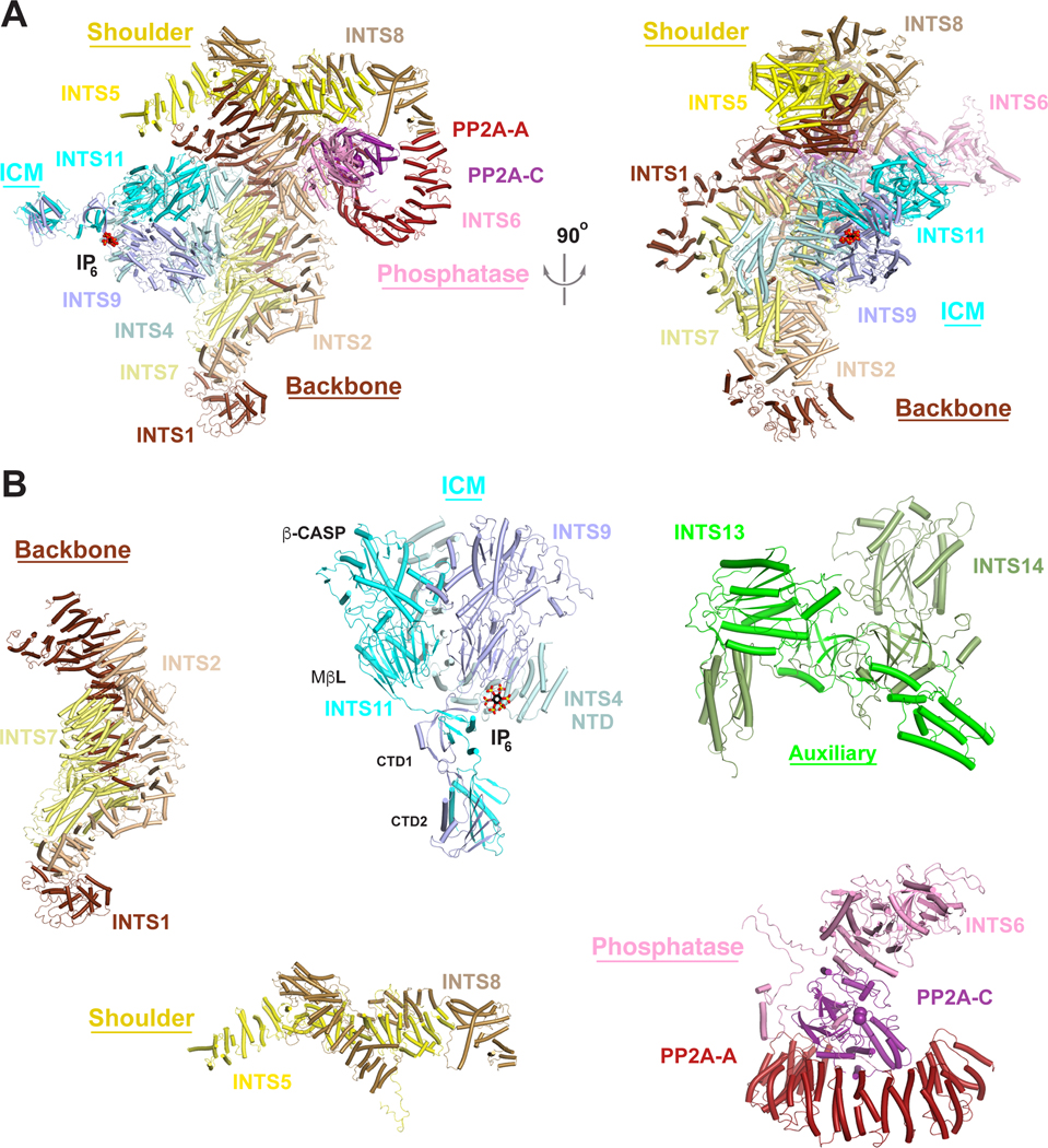
Figure 3. The overall architecture of Integrator in an inactive state.
(A). (Left) Schematic of the structure of Integrator-PP2A complex in an inactive state33, with subunits colored as in Fig. 2. IP6 observed in the structure of Drosophila ICM36 is shown in a sphere model. The metal ions in the active site of INTS11 and manganese ions in the active site of PP2A-C are shown as spheres. (Right) Structure shown at left after 90° rotation around the vertical axis. (B). Structures of the individual Integrator modules. Module structures are derived from the structure shown in panel 3A with the exception of the INTS13/INTS14 structure, which is from39. Structure figures were produced with PyMOL (www.pymol.org).

