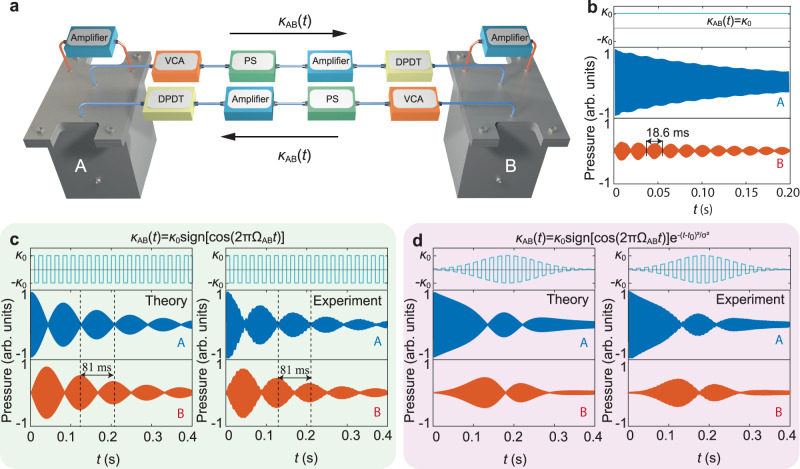
Fig. 2. Temporal quasi-phase matching with the periodically changed couplings.
a Simplified experimental setting for two acoustic cavities with dynamic coupling, which is realized by detecting the sound in cavity A (B) and then feeding it to cavity B (A) through the power amplifier (connection shown as blue lines). VCAs, PSs, and DPDTs are introduced to modulate the coupling amplitude and sign. Two further amplifiers (connection shown as red lines) are employed to balance the cavity loss and to support a long-lifetime cavity mode. b Recorded transient sound waves in two detuned cavities A (blue) and B (orange) with a constant coupling κ0 (cyan line). Due to the phase mismatching, only a small portion of the sound energy in cavity A can periodically transfer to cavity B. c–d Simulated (left panels) and measured (right panels) complete sound wave oscillation between the two cavities with temporal quasi-phase matching condition. The variation of the coupling’s amplitude in (d) is Gaussian. Source data are provided as a Source Data file.

