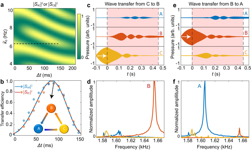
Fig. 4. A frequency-converting circulator based on temporal adiabatic passage.
a Numerically simulated wave transfer efficiencies and as a function of and . The black dashed line denotes the parameter space used in (b). b Simulated (curves) and measured (circles) transfer efficiencies and with . The inset shows the sound circulations with , which are given in the following c–f together with c-d in Fig. 3. The gradient colors denote the one-way frequency conversions. c Recorded sound waves in three cavities. Cavity C is initially excited at for , as denoted by the white arrow. d Fourier spectra of the transient pressures in (c) with , showing the frequency conversion effect from to . e and f are similar as (c) and (d) but with cavity B being initially excited at , showing the wave transfer from cavity B to A with frequency conversion from to . Source data are provided as a Source Data file.

