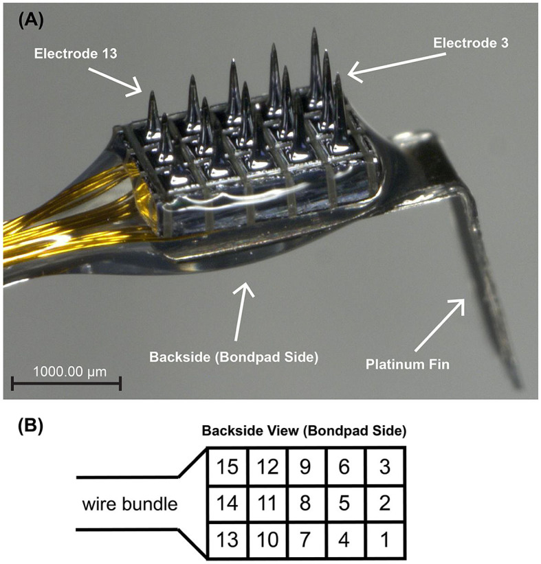
Figure 2.

(A) Micrograph of the 3×5 ANI USEA of the second design. Going along a column, shaft lengths progress from 0.5 to 0.9 mm. The platinum fin at the end of the device facilitates surgical handling during implantation procedures. A 1,000 μm scale bar is shown at the bottom left. Electrodes 3 and 13 and the back side of the array are indicated for orientation purposes. (B) is a schematic representation of the ANI USEA from the back side of the array (i.e., bondpad side) with numbered electrodes.
