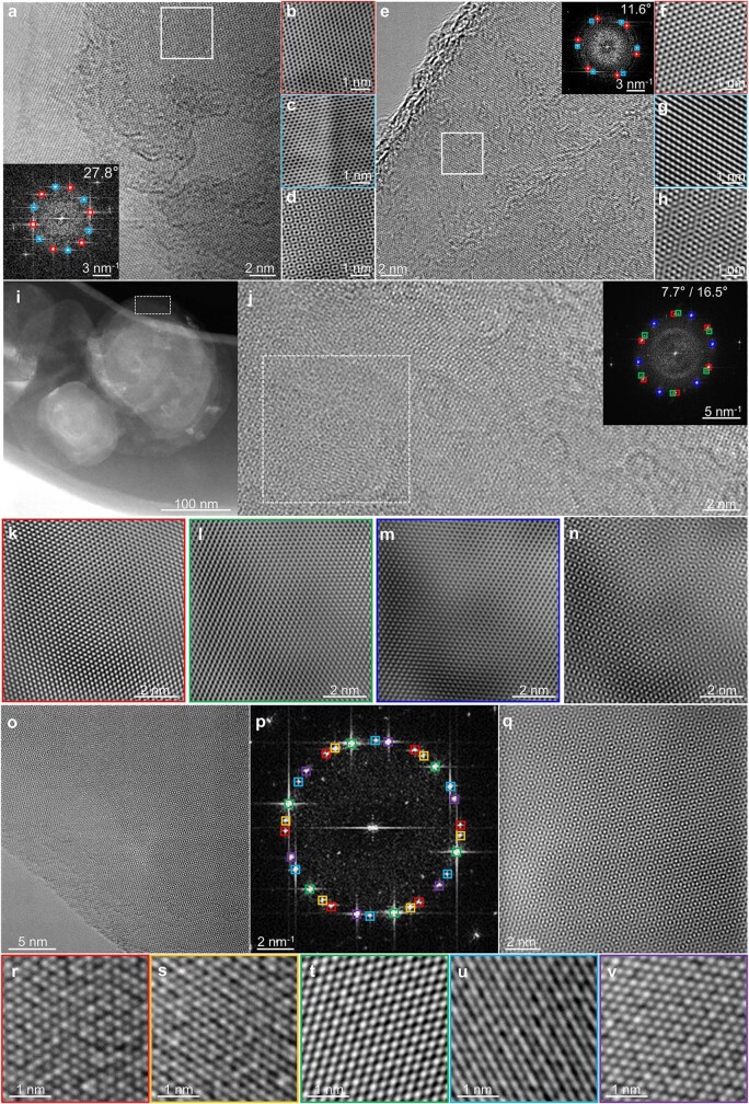
Extended Data Fig. 4. Moiré patterns formed by superimposing of two (a-h), three (i-n) and five (o-v) twisted nanoslices, respectively.
a and e, HRTEM images taken at the edge of the nanoplate. The insets are the FFT patterns from white box areas in TEM images, showing two sets of superimposed diffraction patterns (marked with red and blue) with relative rotation angles of 27.8° and 11.6°, respectively. Note that a is the same as Fig. 1e. b, c and f, g Inverse FFT lattice images derived from FFT patterns. d, Moiré pattern formed by superimposing two sets of lattice images in b and c. h, Moiré pattern formed by superimposing two sets of lattice images in f and g. i, STEM dark field image of the nanoplate in ceramic. j, HRTEM image from the edge area (white dotted box) in i, showing the moiré pattern. Inset is the FFT pattern of white dotted box area in j, which is composed of three sets of diffraction spots. The adjacent twisted nanoslices are rotated by 7.7° and 16.5°, respectively. k, l, and m Inverse FFT lattice images derived from three sets of diffraction spots in FFT patterns marked with various colors. n, Moiré pattern formed by superimposing of three sets of lattice images in k, l, and m. o, HRTEM image taken from the edge of the nanoplate, showing the moiré pattern. p, FFT pattern superimposed by five sets of diffraction spots. q, Moiré pattern superimposed by five sets of lattice images in r-v. r-v, Inverse FFT lattice images derived from the five sets of diffraction spots in FFT pattern marked with various colors.

