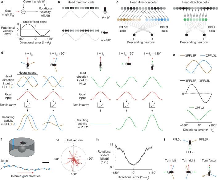
Fig. 1. Comparing model predictions with behaviour.
a, A rotational servomechanism works to keep the angle θ of some device close to a goal value θg. The output is a rotational velocity command that depends on the system’s error (θ − θg). Rotational velocity is close to zero around the goal (θ = θg) and the anti-goal (θ = θg + 180°). Whereas the goal is a stable fixed point, the anti-goal is an unstable fixed point. b, In the Drosophila brain, head direction is represented in Δ7 cells as a sinusoid over two spatial cycles. c, PFL3L, PFL3R and PFL2 populations extract spatially shifted copies of the head direction representation. These three populations are aligned in the fan-shaped body, where they share inputs from putative goal cells (Extended Data Fig. 1c). d, Model: each PFL population adds its head direction input with a shared input from goal cells. This is passed through a nonlinearity and then integrated over space. e, Model: activity of each PFL population versus directional error. f, Data: path of a fly in a virtual environment with a visual head direction cue (a bright bar). Dots indicate 90° and 180° jumps of the environment; here the fly is correcting for all these jumps with rapid turns. g, Mean head direction θ in 10 min epochs with periodic jumps. Radial length denotes the consistency of head direction over time ρ, which ranges here from 0 to 0.8 in n = 56 epochs from 56 flies; 0° is towards the cue. h, Data: mean rotational speed versus directional error, the s.e.m. across flies (n = 46 flies). i, Model: PFL populations have shifted head direction inputs that tile the space of compass directions. Each population detects overlap between its shifted head direction vectors and a shared goal vector. The PFL3L population drives left turning, whereas the PFL3R population drives right turning and PFL2 drives increased rotational speed. Scale bar (f), 30 mm.

