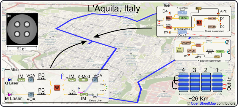
Fig. 2. Illustration of the setup.
Schematic of transmitter (Alice), receiver (Bob) both located at the University of L'Aquila headquarters, and multicore fiber channel. Transmitter. Q (M) Laser Quantum (Monitor) Laser, IM Intensity modulator, VOA Variable Optical Attenuator, PC Polarization Controller, ϕ-Mod Phase Modulator, BS Beam-splitter, FS Free-Space. Receiver. PLL Phase-Locked Loop, ϕ-shifter Piezo Phase Shifter, DWDM Dense Wavelength Division Multiplexer, APD Avalanche Photo-Diode, FM Faraday Mirror. Channel. Channel is formed by concatenating four multicore fibers with four uncoupled cores, each of approximately 6.5-km length. At the endpoint, two cores are connected back into the others, resulting in a 52-km-long two-core fiber link. The multicore fibers are deployed in an underground tunnel in the historical downtown area of the city of L'Aquila, Italy. The map depicting the city of L'Aquila and the span of the multicore fiber is roughly drawn based on the exact map presented in ref. 26. b The cross-section of the MCF. The four cores and the trench design are visible in the photo26.

