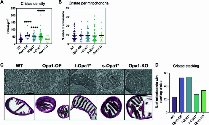
Figure EV2. Cristae analysis.
(A) Cristae density (cristae per µm2) represented as a scatter plot. N refers to number of cells; WT = 33, Opa1-OE = 7, l-Opa1* = 21, s-Opa1* = 28, Opa1-KO = 11. (B) Number of cristae per mitochondria represented as a scatter plot. N refers to number of cells; WT = 51, Opa1-OE = 17, l-Opa1* = 39, s-Opa1* = 55, Opa1-KO = 12. (C) (Top) Summed, projected central slices of cryo-electron tomograms visualizing mitochondria with stacking crista characteristics, supported by 3D representations consisting of their sub compartments (bottom) in indicated MEF lines. Scale bar = 200 nm. N refers to number of cells; WT = 57, Opa1-OE = 17, l-Opa1* = 39, s-Opa1* = 55, Opa1-KO = 12. The representative tomograms for WT, Opa1-OE, l-Opa1*, and Opa1-KO are the same as in Fig. 1A. The representative s-Opa1* tomogram is the same as the second from the left in Appendix Fig. S2A. (D) Graph bar representing percentage of mitochondria with stacking crista formation in each MEF line. N refers to number of cells; WT = 57, Opa1-OE = 17, l-Opa1* = 39, s-Opa1* = 55, Opa1-KO = 12. Data information: Significance of difference is tested relative to WT using Mann–Whitney test; ****p < 0.0001.

