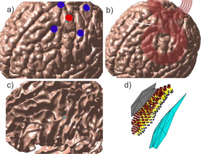
Figure 3.
Source configurations for Connectome Subject 122620 (segmented by the headreco pipeline) for each class of forward problem. (a): TES electrode configuration. A focal ring configuration with one positive (red) and four negative (blue) electrodes is shown positioned above the motor hand area. The cyan sphere denotes the selected target point on the GM surface. (b): TMS coil position above the motor hand area at the gray matter surface. The coil model in use is a MagVenture C-B60. The black line denotes the centerline of the coil, the cyan sphere denotes the selected target point on the GM surface, and the white line denotes the expected primary E-field direction at the target point. (c), (d): EEG cortical current dipole configuration. (c): center of cortical dipole cluster (cyan sphere) shown above the WM surface. (d): 260 finite-length dipoles are placed between the GM (gray) and WM (cyan) surfaces centered on the target point. Current flows along the dipoles from the red endpoints to the blue endpoints along the yellow segments.

