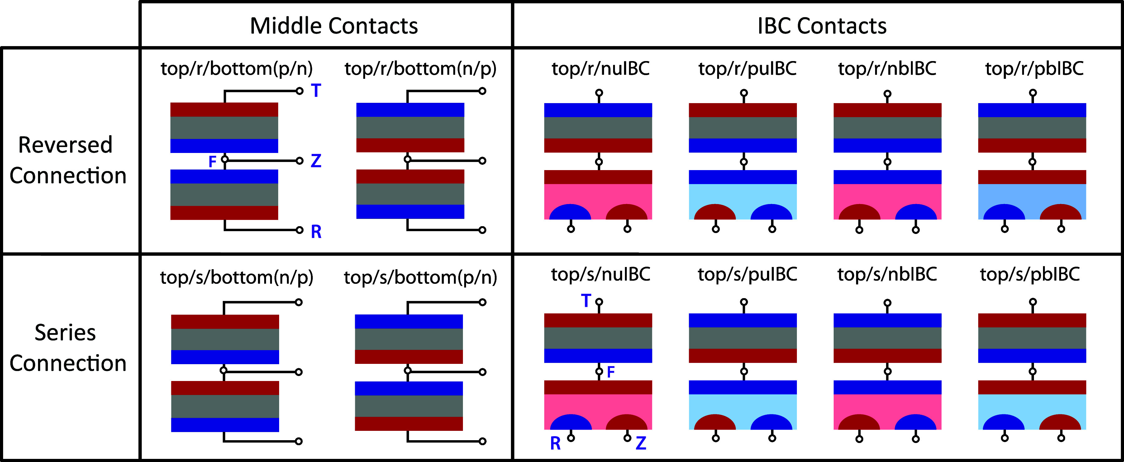
Figure 1.

Mapping the wide variety of three-terminal tandem configurations. In all schematics, n-type materials are red and p-type materials are blue. “Top” is used as a representative top cell, and in a real device would be replaced by the name of the material, e.g. “perovskite” or “GaInP”. The naming terminology above each schematic is explained in detail in the main text. The purple letters (T, F, R, and Z) correspond to the names of the nodes used for different loading configurations.
