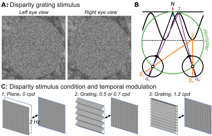
Figure 1.
(A) Random-dot stereopair used in the main experiment depicting a sinusoidal disparity grating (crossed disparity when cross-fused). The dots in the actual experiment were dynamic. (B) Top-down schematic illustration of disparity plane (absolute) and disparity grating (relative plus absolute disparity) stimuli. Fixation point N (nonius lines) is on the zero-disparity plane defined by the horopter (green Vieth-Muller circle). Point 1 (purple) is also on the horopter and angles αL and αR are equal, meaning that the absolute disparity given by αL − αR is zero. Point 2 (orange) is either on a second, disparate plane (dotted line) or on the peak of a disparity grating (sinusoidal line). Here the absolute disparity, βL − βR, is nonzero. The relative disparity is the difference between the two absolute disparities, (αL − αR) − (βL − βR) , and varies depending on the location on the sinewave, but its magnitude is independent of fixation. Disparity along the second plane (dotted line) is constant at a nonzero value. (C) Schematic of disparity plane stimulus (1) that involves the temporal modulation at 2 Hz between crossed disparity, “disparity on,” and zero disparity, “disparity off,” phases. Schematic illustration of disparity grating stimuli (2, 3) that involve 2-Hz temporal modulation between a cyclopean grating portrayed with crossed disparity and a zero-disparity plane. Participants were asked to detect a brief color change on the nonius fixation lines.

