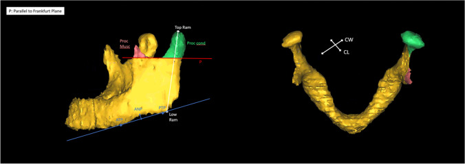
Fig. 1.
Illustration of the measuring points. An example of a 3D model of the mandible. The red line (P) represents a plane parallel to Frankfurt plane, touching the most inferior point of the mandibular notch, that was used to set the inferior boundary of the muscular processus (Proc. Musc.), in red, and the condylar processus (Proc. Cond.) in green. Also the measurements between the most superior (Top Ram) and inferior points (Low Ram) of the mandibular ramus are presented here in white. The blue line shows the line between the anterior and posterior tangent point (ANP and PNP) that was used to assess the depth of the antegonial notch (ANP) in a 90° angle to the blue line. Also the condylar width (CW) and condylar length (CL) are illustrated

