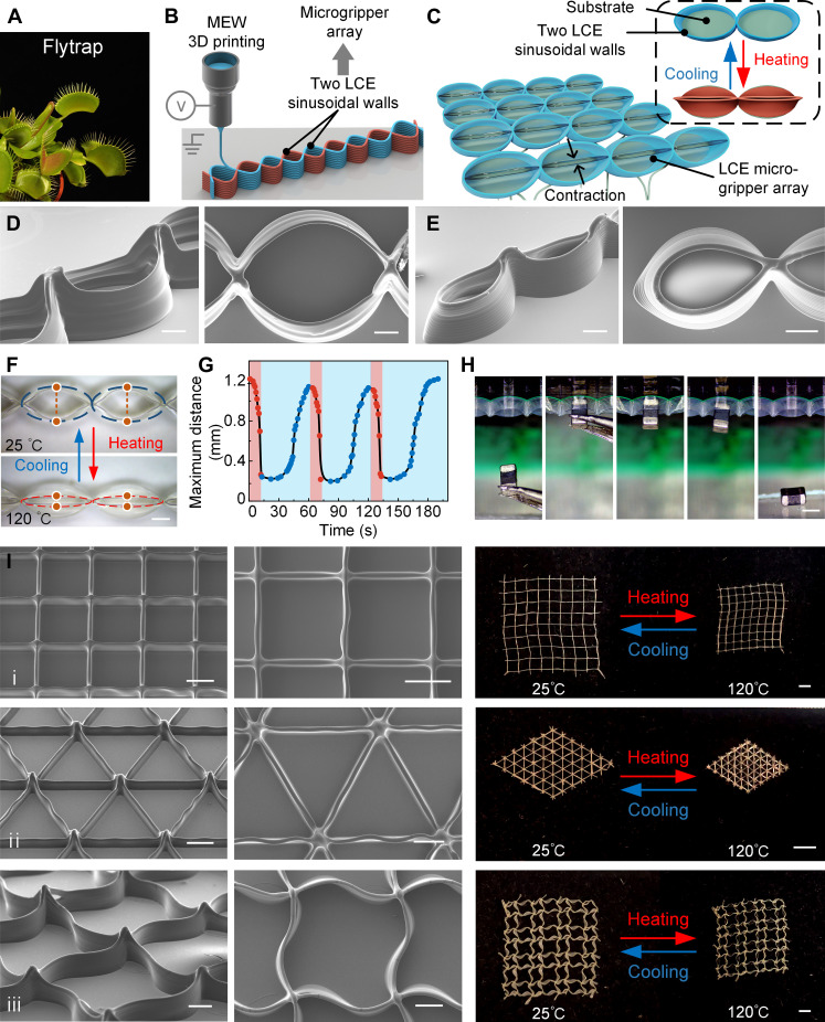
Fig. 4. The 3D MEW-printed flytrap-inspired LCE microgrippers and 3D lattice structures.
(A) Venus flytraps in their closed or open states. (B) Schematic diagram of the LCE microgripper fabrication by MEW. (C) Schematic diagram of the reversible switching process between the open and closed state of the MEW-printed LCE microgripper. (D) SEM images of the LCE microgrippers with a length of 3 mm and a width of 2 mm. Scale bar, 500 μm. (E) SEM images of the LCE microgripper with a length of 1.5 mm and a width of 1 mm. Scale bar, 500 μm. (F) Photographs of the thermal-responsive LCE microgripper in the open and closed states. Scale bar, 500 μm. (G) Cyclic test, where the maximum distance between the two claws of the LCE microgripper changed with time. The maximum distance denoted the distance between the upper and lower points marked on a microgripper in (F). (H) Process of LCE microgripper grasping and subsequently releasing an inductor. The inductor had a length of 2 mm, a width of 1.2 mm, and a height of 0.5 mm. Scale bar, 1 mm. (I) 3D MEW-printed lattice structures. The left two columns display the SEM images of the lattice structures, and the rightmost column shows the photographs of the lattice structures before and after thermal contraction. A square lattice structure, a triangular lattice structure, and a quadrilateral lattice structure composed of sinusoidal curved LCE walls are shown in the first, second, and third rows, respectively. Scale bars, 500 μm (SEM images) and 2 mm (photograph).

