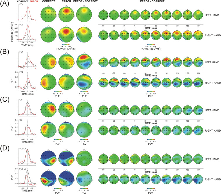
Figure 4.
Theta TF component (3.5–7 Hz) of response-related correct and error potentials elicited by left- and right-hand motor responses (A) Total power, (B) Temporal synchronization (PLF), (C) Region-specific connectedness (regional PLV), (D) FCz-guided synchronization FCz-PLV. Left panel—Extracted theta scales at relevant mid-line, contra-, and ipsi-lateral electrodes (explained in the text); Middle panel – Topography maps for correct, error and error minus correct difference at the time of maximal expression (peak) of the signal at contra-lateral central electrodes; Right panel—Dynamic topography difference maps (error minus correct). Response onset at 0 ms.

