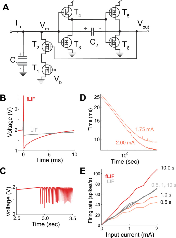
Figure 2.
The fractional leaky integrate-and-fire circuit. (A) Schematic diagram. (B) Action potential generated by the classical (LIF) and fractional LIF (fLIF) circuits. (C) Example of spike train generated in response to a constant input. Spikes were clipped for clarity. (D) Inter-spike interval as a function of time and constant input current. (E) Firing rate in the LIF and fLIF circuits. The firing rate in the fLIF circuit was calculated using different time windows from the onset of the first spike.

