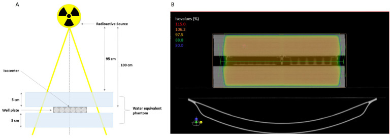
Figure 6.
(A) Representative scheme of the standard irradiation setup to deliver 6 MV irradiation to the isocenter of the cell-well plate using a linear accelerator. The plate was plated between water-equivalent phantoms to simulate the tissues and depth. (B) Illustrative image of the treatment plan where the isodose lines are visible, surrounding the treatment area with at least 95% of the dose.

