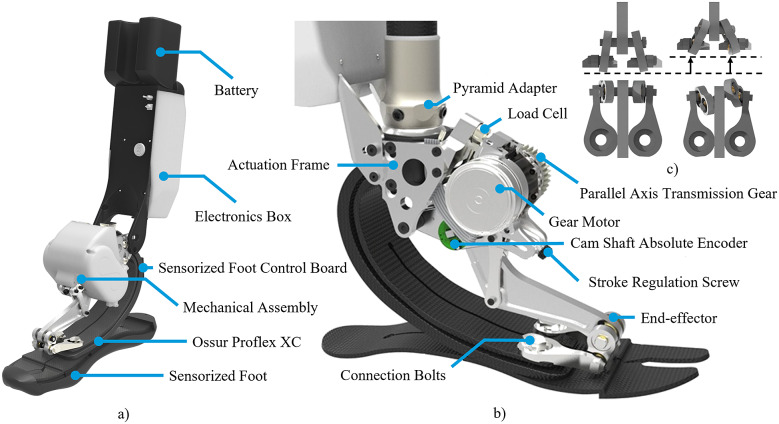
Figure 2.
(a) Overview of the WRL TTP and its main components. (b) Rendering of the lateral view of the mechanical assembly of the WRL TTP without the cover and the sensorized foot. (c) Front and top view of the differential mechanism connecting the end-effector with the ESAR forefoot. The figures on the left show the differential mechanism in tension, while the ones to the right show the safe self-folded configuration.

