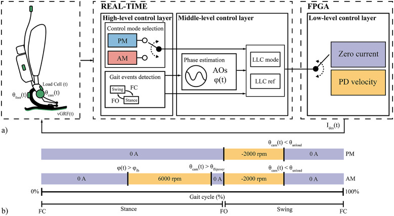
Figure 5.
(a) Layered control architecture of the WRL TTP. The control mode selection in the High-Level layer is performed via manual selection on the remote GUI. (b) Graphical representation of the mode-specific assistive strategy in the middle-level layer. The violet parts indicate a low-level control in current (desired output in A). The yellow parts indicate a low-level control in velocity (desired output in motor rounds per minute).

