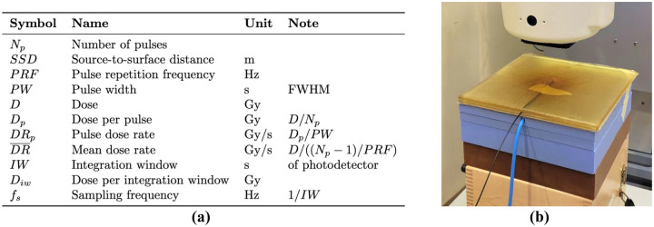
Figure 1.
(a) Parameter symbols used in this work. (b) Measurement setup of the scintillator probe under the Mobetron beamline. Tape was used to secure the probe in place between the two sheets of semi-transparent bolus material. The white treatment head of the Mobetron is visible at the top of the image. The blue cable from the ionization chamber (only included during conventional dose rate measurements), embedded in the 2 cm of solid water directly below the bolus material, is also visible.

