. 2024 Feb 26;12:RP89968. doi: 10.7554/eLife.89968

Figure 6. To quantify how the recruitment of the pectoralis muscle changes during the downstroke, we consider the balance of 3D angular momentum by calculating the associated torques.

(A) The forces are as in our 1D power balance (Figure 5A), but instead of considering the entire bird, we evaluate the balance around the left shoulder joint. Consequently, body mass becomes irrelevant, and instead a reaction force (F0; cancels out) and moment (M0; assumed small compared to other torques) at the shoulder joint appear. (B) The pull angle between the humerus and the pectoralis, θp, dictates how effectively the pectoralis exerts torque on the wing. The inset shows the corresponding lateral view with subscript ‘b’ referencing the body frame while no subscript indicates world frame. The pull angle depends both on the humerus orientation during the wingbeat and pectoralis muscle fiber recruitment. (C) During downstroke, the pull angle that we compute for the doves in slow flight (black line) is lower than chukars during wing-assisted incline running (Heers et al., 2016) (gray line). However, if pectoralis moment is used to tension the supracoracoideus tendon during the second half of the downstroke to more finely tune the wingbeat, the pull angle would necessarily increase to values higher than plotted here and shift the curve towards chukar values. (D, E) The 3D vector direction (purple: +xb: cranial, -xb: ventral; green: +yb: medial, -yb: lateral; orange: +zb: dorsal, -zb: ventral) and stress magnitude (black), associated with the pectoralis pull on the humerus, were computed using the pull angle and the modeled position of the humerus under the assumption that it is the only muscle generating a moment on the wing during the downstroke.

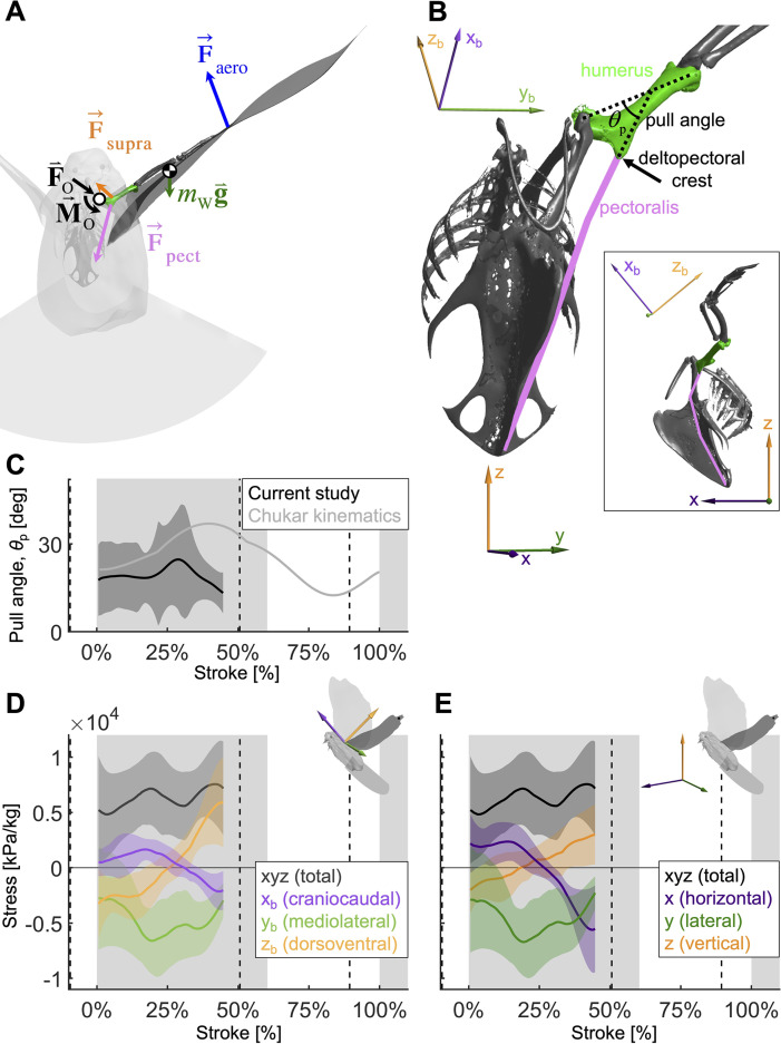
Figure 6.

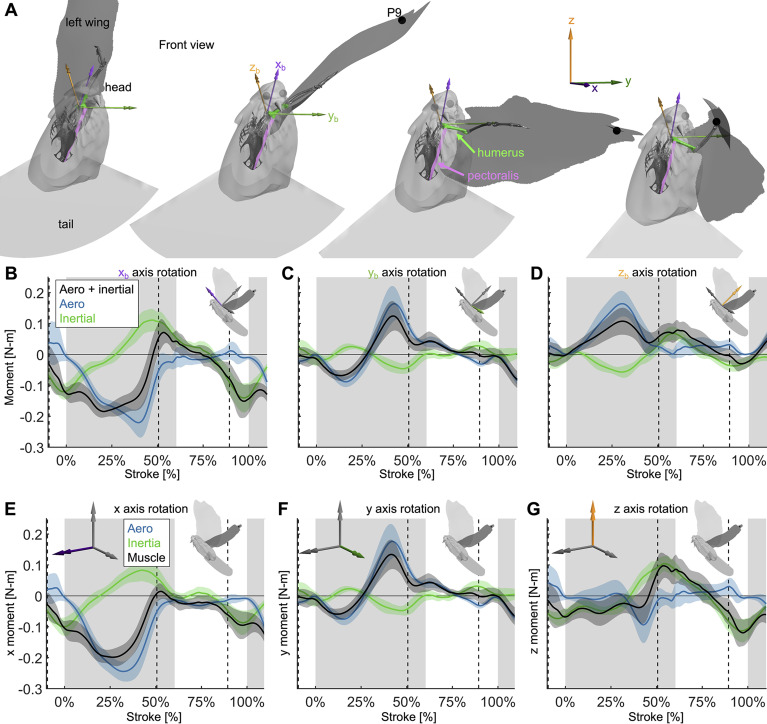
Figure 6—figure supplement 1. Extra details are added to Figure 6 to demonstrate how the 3D angular momentum balance works.

Figure 6—figure supplement 1.

(A) The frontal view of the dove at 0, 33, 67, and 100% of the downstroke is shown with the right wing surface removed. The skeleton was positioned based on the shoulder joint and wing kinematics, with only the humerus (green), radius/ulna, and manus permitted to move relative to the body (radius/ulna and manus are used for visualization only). The skeleton was used to define a new ‘body’ reference frame, where the xb axis points in the cranial direction (aligned with the thoracic vertebrae of the dove), the yb axis points in the distal direction (aligned with the y direction in the Newtonian reference frame if the dove flies straight from the takeoff perch to the landing perch), and the zb axis points in the dorsal direction. For visualization, the pectoralis was modeled as a path along points that are rigidly attached to the skeletal body and humerus. (B–D) Similar to the 1D power balance (Figure 5), the 3D required muscle moment (black) is composed of the vector sum of the aerodynamic (blue) and inertial (green) 3D moments. (B) The flight muscles need to pull ventrally on the wing (negative moment in the cranial, xb, axis) during the downstroke, to oppose lift and drag, which point vertically up (Figure 3A, Figure 3—figure supplement 1C). During the upstroke, inertial effects dominate, such that the flight muscles pull dorsally during stroke reversal into the beginning of the upstroke and ventrally at the end of the upstroke. (C) In the lateral (yb) axis, the required muscle moment is primarily due to aerodynamics rather than inertia. At the beginning of the downstroke, the wing is toward the posterior of the dove, creating a positive yb aerodynamic torque, which is balanced by a muscle moment to supinate the wing. At the end of the downstroke, the wing is toward the anterior of the dove, so the opposite is true. (D) Because the dorsal (zb) axis of the dove is partially pointed horizontally backward, the lift and drag in the positive vertical direction (Figure 3—figure supplement 1C) generate a cranial moment during the downstroke. The flight muscles generate a caudal moment during the downstroke to oppose the aerodynamic moment. (E–G) The same 3D angular momentum balance data is shown as in (B–D), but in the familiar Newtonian reference frame shown in Figure 1C. (E) Moments in the x-axis. (F) Moments in the y-axis. (G) Moments in the z-axis.