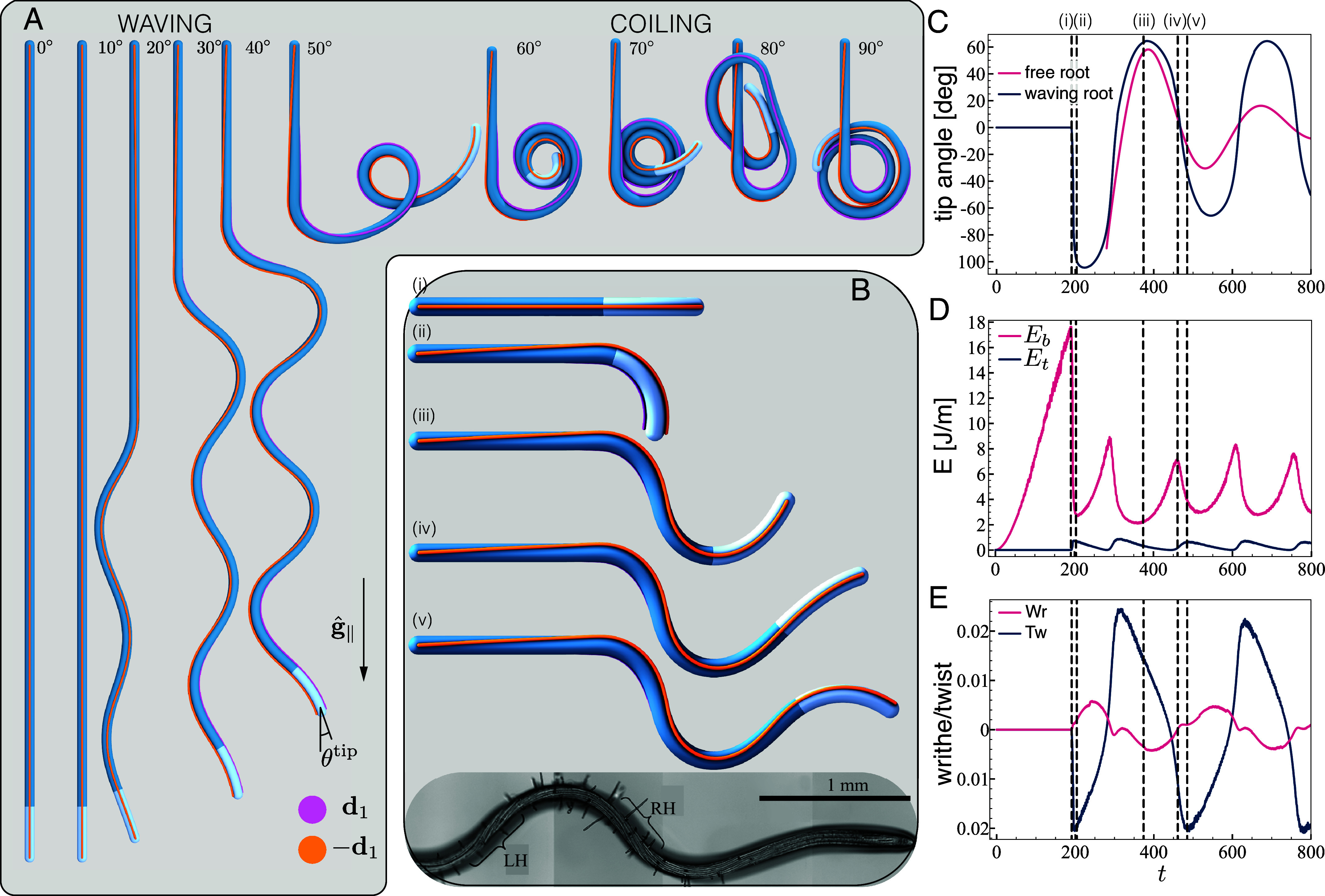
Fig. 2.

Simulations reproduce waving and coiling. (A) Final configurations. Top view of final configurations of simulations for tilt angles , with . Pink and orange lines represent the direction of the vectors describing the material frame along the organ. The local planar angle is the angle between the projection of the organ tangent on the tilted plane, and the projection of the direction of gravity . (B) Snapshots of waving dynamics. Five snapshots during the developing waving pattern for a root at , with local gravisensing, , and . Stages (i) and (ii) depict the first symmetry breaking due to an elastic instability that reduces bending energy by twisting sideways. Between stages (iii) and (v) left-handed twist is being accumulated in the mature zone as the root turns clock-wise (evident by following ), in line with observed twisting cell files (26). (C–E): Properties of the growth zone during the development of a waving pattern, corresponding to the root in (B). Dashed lines represent the snapshots in (B), and time is shown in number of time-steps. (C) Planar tip angle (blue). For comparison, we show the behavior of a corresponding free organ (pink line), that is of a root growing without substrate but characterized by the same initial angle (with respect to gravity) of the waving root (blue line). Both profiles present oscillations with a similar period; however, in the absence of interactions with the plane, the oscillations decay in time. (D) Average elastic bending energy and twisting energy in the growth zone. (E) Total writhe Wr and twist Tw in the growth zone.
