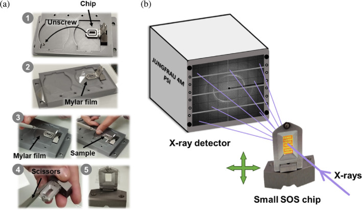
FIGURE 1.

Sample loading and data collection setup at the ID29 beamline. (a) Steps 1–5 for loading the small SOS chip: (1) unscrew and place the chip in the chip holder; (2) place a mylar film over the chip; (3) apply the sample on the mylar film, place another mylar film on top and screw again; (4) remove the excess mylar film; and (5) chip loaded and mounted. (b) Schematic diagram of the setup. A 1% bandwidth x‐ray beam with a pulse length of 90 μs at repetition rate of 231.25 Hz was used. The x‐rays hit the sample that is immobilized in the small SOS chip, which moves from left to right in a zig‐zag pattern across the X–Y axes. Diffraction is collected on a JUNGFRAU 4M detector.
