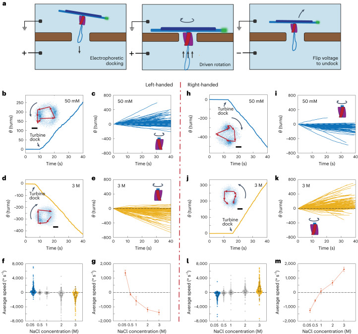
Fig. 3. Sustained unidirectional rotation of DNA origami turbines in an applied field.
a, Schematic of a DNA turbine docking into and undocking from a nanopore on applying a transmembrane voltage. b, Typical cumulative angle versus time for a left-handed turbine for a 100 mV bias voltage in 50 mM NaCl, showing a sustained rotation over hundreds of turns. Inset: corresponding heatmap (blue pixels) of single-particle localizations for the tip of the DNA bundle with an example trajectory of the labelled tip overlaid. c, Cumulative angular-displacement curves for left-handed turbine-driven DNA bundles as in b but for n = 210 turbines. d,e, The same as b,c but in 3 M NaCl electrolyte (n = 159). f, Average rotation speed for left-handed turbines in NaCl concentrations of 50 mM, 500 mM, 1 M, 2 M and 3 M (n = 198, 77, 86, 252 and 150 respectively). g, Mean rotary speed of left-handed turbines for various buffer salt concentrations (Supplementary Fig. 8). Error bars are s.e.m. h–m, The same as b–g but for right-handed DNA turbines (ni = 174, nk = 298, nl = 116, 252, 164, 200 and 260. respectively). In all box plots: centre line, median; box limits, upper and lower quartiles; whiskers, 1.5 × interquartile range. All scale bars are 100 nm.

