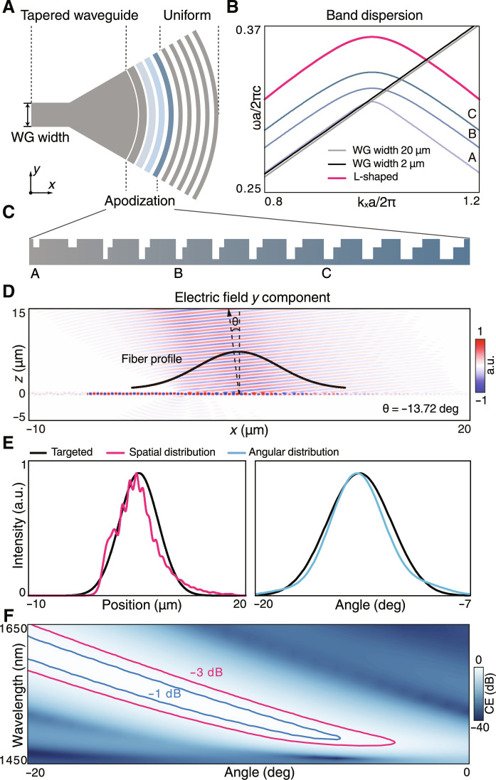
Fig. 2. Design of unidirectional grating coupler.
(A) Top view of the schematic grating coupler which is divided into tapered-waveguide, apodization, and uniform regions. (B) Band structures of the grating and waveguides, in which the dispersion of uniform grating adiabatically transits to that of the waveguide. Momentum and group velocity matches are optimized by engineering the apodization region. (C) The enlarged view of the apodization region. (D) The electrical field distribution (Ey) at 1550 nm of the unidirectional grating coupler excited by the mode source. The upward radiation has a −13.72∘ tilt angle that agrees with the UGR. (E) The spatial and angular distributions of the upward radiation demonstrate that the radiating Gaussian beam aligns well with the target fiber. (F) The map of coupler-to-fiber CE over the wavelengths and alignment angles in which the −1- and − 3-dB thresholds are marked by blue and red contours.

