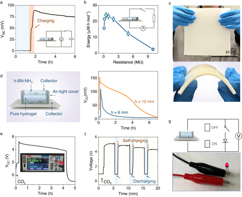
Fig. 4. Scaling up and practical demonstration CO2 adsorption electricity generator.
a CO2 adsorption induced electricity was stored by charging a commercial capacitor (0.5 µF). Blue, yellow background indicate the potential of the capacitor at initial and charged status, respectively. b Energy harvested from the generator in a one-adsorption cycle when connected with different external resistors. The total electricity was calculated according to the current curve as a function of time monitored by the source meter: . Error bars are standard deviations from three tests. c Photographs of a large size of NAH composite fabricated by casting method depicting scalability. d Schematic of the vertically staked generator and the power generation from the devices with different thicknesses (h indicates the total thickness of the devices). By using the vertically stacked generator, the accelerated ion transport leads to a prompt response to the CO2. The induced Voc of the generators reached their peaks in several seconds after feeding CO2 into the testing box. In addition, the thicker the generator, the higher the peak Voc, and the longer the electrical signals last. e Electricity generation by five parallel connection of vertically stacked generator groups comprising ten generators in series (5 × 10). Inset is the photograph of the output voltage measured by the source meter. f Generators in parallel and series (5 × 10) were used to power a light-emitting diode, the blue and red background indicate the status of the switch (on and off). The fluctuations on the Voltage ascending curve likely indicate that the charging speed is influenced by the characteristics of the external circuit. g Photograph of the emitting diode (Broadcom Inc. Bulb size: 3 mm, forward voltage: 1.6 V, forward current 1 mA) powered by the integrated CO2 generators.

