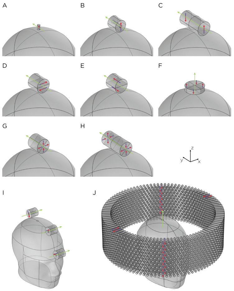
Figure 1.
Dimensions, placement, and magnetization directions for ten configurations of rotating magnets (A–J). Model of single magnets in the (A) TRPMS and (B) sTMS systems. (C–H) Model of single magnets with multiple segments of different magnetization directions. (I) Model of the full sTMS system. (J) Model of the wide-bore, low-frequency magnetic spinner. The green arrows show the rotation axes, with the rotation direction determined by the right-hand rule. The red/blue arrows show the direction of the magnetization.

