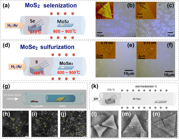
Fig. 26.
Synthesis of TMC alloys by atomic substitution. a, d Schematic illustration of the experimental set-up for the selenization/sulfurization process. b, e Optical micrographs for the as-synthesized MoS2/MoSe2. c, f Selenized (sulfurized) MoS2/MoSe2 (at 800 °C) on sapphire substrates. Reproduced with permission [150].
Copyright 2014, Frontiers Media S.A. g Schematic setup for the post-growth substituting. h-j Atomically resolved ADF-STEM images showing the atomic structure of Te-doped MoS2 monolayer at different growth temperature. A number of bright sites corresponding to the local Te sites can be distinguished (marked with yellow circles). Scale bar: 1 nm. Reproduced with permission [151]. Copyright 2018, IOP Publishing. k Schematic illustration for the selenization process. l-n AFM images for the MoS2 flake l before and m after, n selenization at 800 °C. Reproduced with permission [184]. Copyright 2014, John Wiley and Sons

