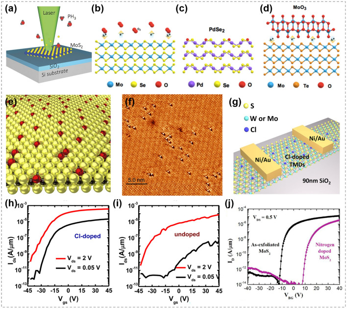
Fig. 30.
Nonmetal elements substitution doping in TMCs. a Schematic diagram of the laser-assisted doping method. Reproduced with permission [197].
Copyright 2016, John Wiley and Sons. b Illustration showing charge transfer from oxygen molecules. c Isoelectronic substitution of chalcogen atoms in TMCs. d Illustration showing charge transfer from oxide. Reproduced with permission [198]. Copyright 2020, Springer Nature. e Schematic representation of atmospheric oxygen atoms getting adsorbed on a MoS2 monolayer. f Scanning tunneling microscope image of O atoms (bright spots) absorbed at S vacancies (dark triangles) sites. Reproduced with permission [199]. Copyright 2018, Springer Nature. g Schematic of Cl-doped few-layer WS2 back-gate field-effect transistors (FETs). h Transfer characteristics of the device (Cl-doped). The Ion/Ioff ratio is about 4 × 10⁶ and 3 × 10⁷ at Vds of 2 and 0.05 V, respectively. i Transfer characteristics of the device (undoped). The Ion/Ioff ratio is about 2 × 10⁶ and 1.1 × 10⁴ at Vds of 2 and 0.05 V. Reproduced with permission [194]. Copyright 2014, American Chemical Society. j IDS-VGS characteristics of multilayer nitrogen-doped MoS2 FET. Reproduced with permission [195]. Copyright 2016, American Chemical Society

