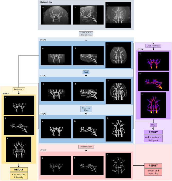
Figure 4.
Lusca pipeline applied for morphological 3D magnetic resonance angiography (MRA) stack analysis. For 3D perception the anatomical planes (a) coronal, (b) sagittal and (c) transversal are shown. Blue, yellow, red, and violet squares represent image segmentation, area, number and intensity, length and branching, and width measurements respectively. The anatomical landmarks of MRA stacks used to standardize the volume and position of the maximum intensity projection ROIs (Optional step, grey square). Vessels on the input images in step 1 segmented from the background with TWS in step 2 and, after area and intensity thresholding, the step 3 segmented image is acquired. In step 4, after redirection of segmented image to the input image, the area, number, and intensity are obtained. For length and branching measurements, in step 3 the image undergoes skeletonization and analysis. Width is calculated by applying Local thickness mask on the image from step 3 to get step 6 image. Simultaneously, the threshold is applied to the 32-bit image from step 5, and after subtracting 255 values NaN for the background and 0 for skeleton pixels are obtained. Images from steps 5 and 6 are added to get step 7 image that serves for width calculations.

