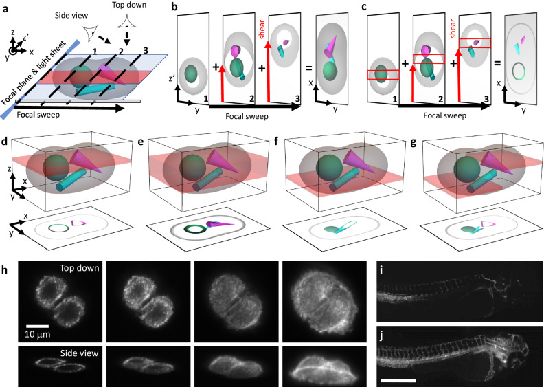
Fig. 1. Concept of projections with parameter selection (props).
a Schematic overview of the imaging geometry in oblique plane microscopy (OPM) and lattice light-sheet microscopy (LLSM). The sample is rapidly scanned with a light sheet (blue) and corresponding focal plane, which is termed a “focal sweep”. If the focal sweep is completed during one camera exposure, an optical projection is formed. b Translating the image on the camera (red arrow labeled “shear”) during a focal sweep results in projections under different viewing angles. On the right, a top-down projection along the z-axis is shown. c When a rolling shutter (red boxes) is synchronized to the shear translation along the camera, a projection of a sub-volume (red shaded area in a) is formed. d, e Schematic illustration of varying the projection depth with the rolling shutter width. The red-shaded volumes illustrate the regions of the sample that are projected below, illustrated as a top-down view. f Illustration of shifting the projection volume axially by introducing a time delay between the rolling shutter and the focal sweep and shearing. g A nonlinear scanning waveform results in an axial change within the projection volume. h LLSMprops imaging of A375 cells labeled with F-tractin-EGFP with varying projection depth, top row: top-down view, bottom row: corresponding 45° viewing angle. The imaging experiment was repeated independently 3 times with similar results. i, j Mesoscopic OPMprops imaging of zebrafish vasculature, labeled with Tg(kdrl:EGFP), over a projection depth of 4 and 362 microns, respectively. The imaging experiment was repeated independently 4 times with similar results. Scale Bar: h: 10 microns, j: 500 microns.

