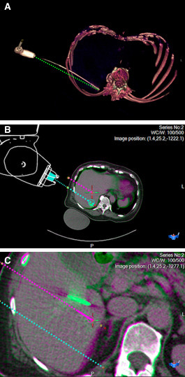
Figure 4.

Example images from a microwave ablation procedure for two breast cancer liver metastases in a 70-year-old woman. (A) Volume rendered CT image showing the antenna path, and an annotated straight dotted green line to illustrate bending of the 17-gauge x 20 cm microwave ablation antenna. (B) Snapshot of fused CT images (before and after needle placement) from the MAXIO software showing accurate first antenna placement, with planned needle path (dotted blue line), vs. antenna tip (solid green) showing clinically acceptable path and tip deviation of 5mm each. (C) Fused CT images, showing less accurate antenna placement for the other lesion, with planned needle path (dotted pink line), vs. antenna tip (solid green) showing path and tip deviation of 16 mm and 20 mm respectively, necessitating manual repositioning.
