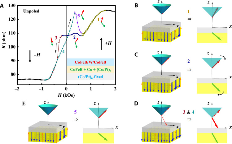
Fig. 2. Magnetoresistance measurements for MTJs under OOP magnetic field with unpoled PMN-PT.
(A) R-H curve for the MTJ pillar (10-μm diameter) between +2000 and −2000 Oe after presetting at +7000 Oe. The curve is highlighted in five sections with five colors numbered 1 to 5 as shown near the curve. The bottom inset is the structure of the MTJ stack, including FL (red), CoFeB+Co + (Co/Pt)3 in RL (green), and (Co/Pt)6 in RL (blue). (B to E) Left: The blue and orange arrows represent the nonideal magnetization directions that change with the sweeping of the magnetic field (detailed in fig. S2A). Right: The red and green arrows represent the equivalent moment directions of the FL and RL [also shown near the corresponding positions in (A)], respectively, corresponding to the five highlighted sections according to the resistance equivalent in tunneling.

