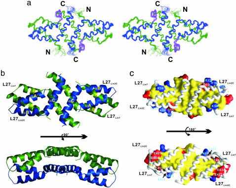
Fig. 1.
Structure of the mLin-2/mLin-7 L27 tetramer complex. (a) Stereoview showing the backbone of 20 superimposed NMR-derived structures of the tetramer complex. L27Lin7 is shown in green, L27Lin2C is drawn in blue, and the linker connecting L27Lin7 and L27Lin2C is in purple. (b) Ribbon diagram of a representative NMR structure of the tetramer complex, colored as in a. A prime after each secondary element (e.g., αA′) in L27Lin2C is used to indicate the same secondary structure as in L27Lin7.(c) Surface representation showing the packing interface of L27Lin7/L27Lin2C.In Upper, L27Lin7 is in the surface representation, and L27Lin2C is in the worm model. In Lower, L27Lin2C is in the surface model, and L27Lin7 is shown in the worm model. The hydrophobic residues are in yellow, the positively charged residues are in blue, the negatively charged residues are in red, and the polar residues are in white.

