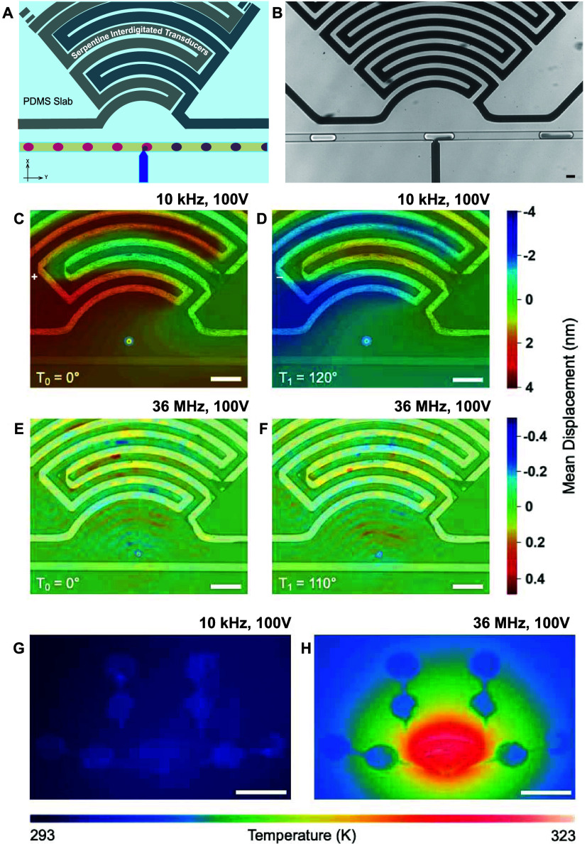
Figure 1.
Characterization of a droplet-based injection device: (A) Illustration of the manipulation area of the device. At the T-Junction, the surfactant-stabilized interface of the passing droplets (pink) is disrupted, enabling the injection of the fluid phase of the injection channel (purple). (B) Bright-field image of the device demonstrating the injection into a surfactant-stabilized water-in-oil droplet. Scale bar: 30 μm. (C–F) Microscopy-based laser Doppler vibrometry (LDV) measurements of the device on LiNbO3 from two frequency domains at time points that attribute to different amplitudes (1 Amplitude: Tπ = 180°; LDV displacement in the range: 0–180). (C, D) LDV measurements obtained while operating the device at 10 kHz and 100 V. The form of the acoustic field, visualized by the color map overlay of the mean displacement field, demonstrates a pressure wave with displacements in the nanometer range. (E, F) Device operating at 36 MHz and 100 V with the mean displacement mapping showing the generation of a focusing SAW with an order of magnitude lower displacement. Scale bars: 100 μm. (G, H) Infrared images of the device on LiNbO3 after operating for 6 s at two frequencies of interest. For panel (G), the frequency is set to 10 kHz, the input voltage is set to 100 V, and the thermal increase is negligible. For panel (H), the frequency is set to 36 MHz and the input voltage to 100 V. In the high-frequency range, there is a thermal increase up to 30 K in the region of the IDT. Scale bars: 2 mm.

