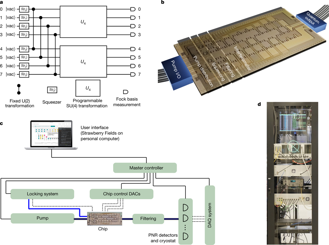
Fig. 1 |. Overview of apparatus.
a, Equivalent quantum circuit diagram illustrating the functionality of the photonic hardware. Up to eight modes initialized as vacuum are squeezed with squeezing parameters and entangled (via the fixed two-mode unitary transformation U(2) equivalent to a 50/50 beam splitter with the relative input phase set to produce two-mode squeezing at the output) to form two-mode squeezed vacuum states. Programmable four-mode rotation gates (SU(4) transformation, represented by the large boxes labelled ) are applied to each four-mode subspace. All eight modes are individually read out by measurements in the Fock basis. b, Rendering of the chip (based on a micrograph of the actual device) showing fibre optical inputs and outputs, and on-chip modules for coherent pump power distribution, squeezing, pump filtering and programmable linear optical transformations. c, Schematic of full apparatus and control system. Solid (dashed) black lines indicate digital (analogue) electronic signals; blue lines indicate optical signals. DAC, digital-to-analogue converter; DAQ, data acquisition; PNR, photon number resolving. d, Photograph of entire system (except for photon-number-resolving detector hardware), which has been fitted into a standard server rack.

