
Figure 1. RF remapping and the recording paradigm.
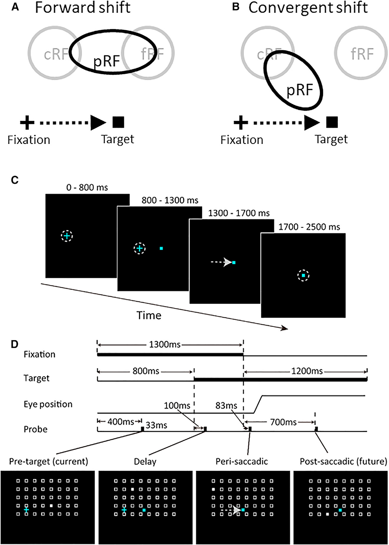
The cross, square, and arrow represent the initial fixatio n point, saccade target, and saccade vector, respectively.
(A and B) Two types of perisaccadic RF remapping have been reported: (A) forward shift in the saccade direction and (B) convergent shift toward the target. The labels are explained below.
(C and D) We used a delayed saccade task for single-unit recordings: (C) the trial sequence, with probes omitted and the dashed circles representing eye positions, and (D) the detailed time course. Four probes were flashed, one for each of the four epochs: pre-target (current), delay, perisaccadic, and post-saccadic (future). A cell’s RF mapped from these periods will be denoted cRF, dRF, pRF, and fRF, respectively. (No dRF is included in A and B, as previous studies did not measure it.) For each epoch, the probe stimulus (filled white squares in the bottom row) appears randomly at one of the spatial array positions (open white squares, not shown in the experiment). The array size and location were tailored for each cell according to pilot mapping.