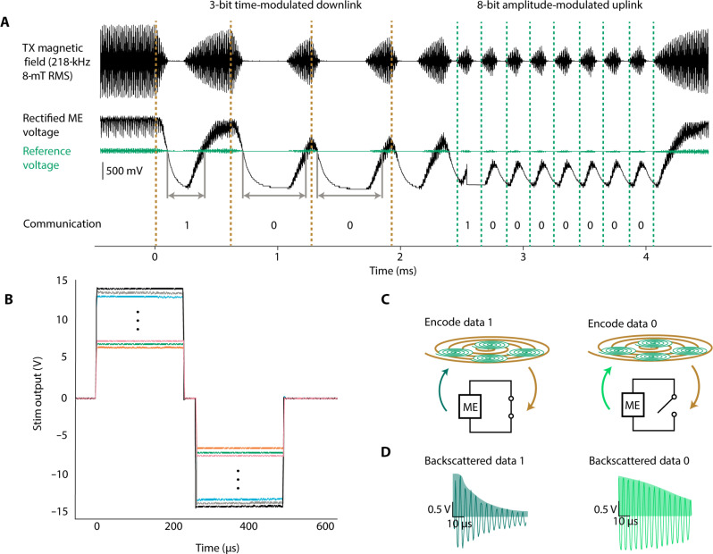
Fig. 2. Wireless communication protocol and device outputs.
(A) Communication protocol for the DOT showing downlink of message 0b100 and uplink of message 0b10000000. (B) Digitally programmable stimulation output pulses showing 250-mV increments between settings. (C) Schematic showing how digital data are encoded by passive ME backscatter. Bits 1 and 0 are encoded by switching the nodes of the ME film between short (data 1) and open (data 0). The films are excited by the transceiver field, and the resulting ringdown field is measured from differentially paired pickup coils while the excitation field is off. (D) Examples of the measured ringdown field during a 1 with a time constant of 40 μs (dark green) and 0 bit with a time constant of 91 μs (light green). Data are decoded as an integration of the positive half of the signal (shaded).

