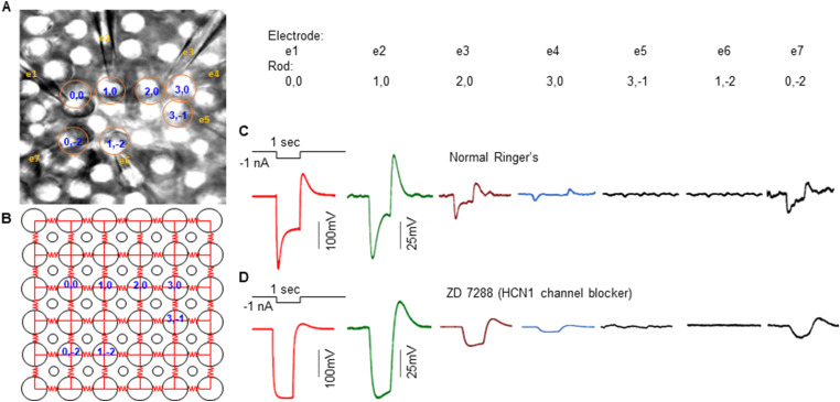
Figure 1.
A, Locations of seven rods recorded in flat-mounted salamander retina with the multiple patch electrode recording system. RodXY are rod locations in the 2D array and e1–e7 are electrode numbers. B, Original locations of the seven rods before recording, as rods were slightly pushed from original positions (yellow circles) by the patch electrodes. Large circles, rods; small circles, cones. Red resistors are coupling resistance between rods (coupling resistance between rods and cones are much higher and thus not shown). C, Voltage responses of Rods1,0; 2,0; 3,0; 3,−1; 1,−2; and 0,−2 to a −1 nA current step (1 s) injected into Rod0,0. D, Repeating experiments in C in the presence of 100 µM ZD7288.

