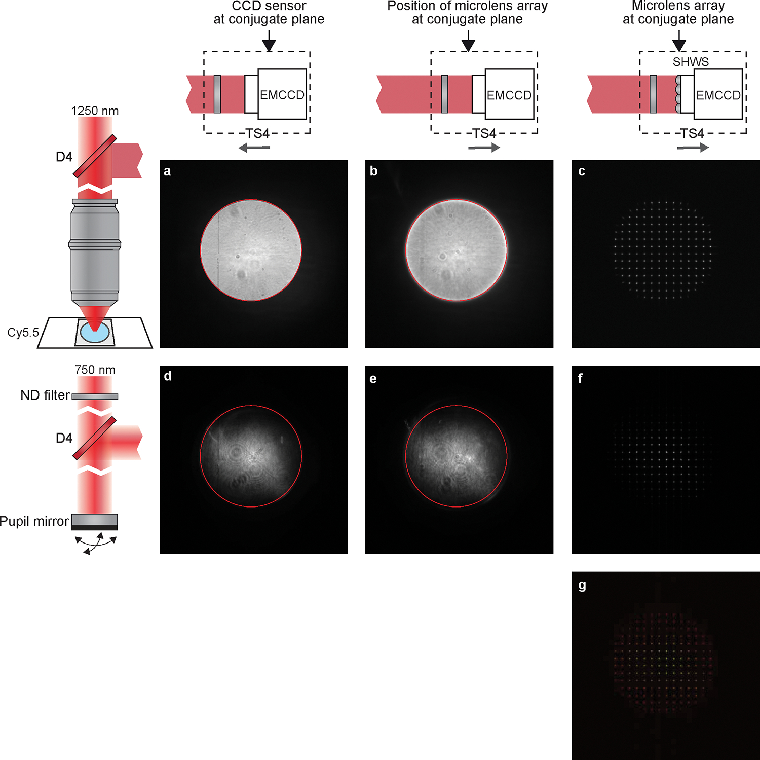
Figure 10 |. AO Calibration preparation.

a to f, Images obtained on the EMCCD before the AO Calibration. Left column, diagram showing the light source for the EMCCD images. a to c was taken with the Cy5.5 fluorescence, d to f used the femtosecond laser beam reflected by a mirror at the pupil plane. Upper row, diagram showing the position of the EMCCD along the optical axis. a and d were taken by the EMCCD at the conjugate plane (P1). c and f were taken by the SHWS of which the microlens array is at the conjugate plane (P2). b and e were taken with EMCCD at the same position as c and f (P2) but no microlens array was placed on the light path. The edge of bright disk in a was indicated by a red circle in image a, b, d, and e, showing that the bright disks in the four images are concentric. g, Merge of c and f. It is critical to the AO calibration that a, b, d, and e are concentric, and that c and f are overlapped.
