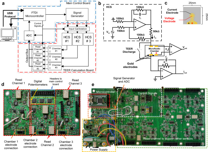
Figure 2: Microphysiological system’s supporting electronics.
a) Block diagram showing the flow of signal conditioning and processing. b) Read channel circuit, responsible for supplying stimulus signal and reading output voltage and current signals directly from the sensor electrodes inside the chamber. c) The sensor electrodes on glass substrate, outer ring electrode is the current electrode, and the middle circle is the voltage electrode. d) TEER acquisition board contains all read channels, digital potentiometers, connectors for the electrodes, and connectors to the main control board. e) Main control board which has the power supply, signal generator and ADC, microcontroller, and control signals.

