Abstract
This study explores the potential of combining periodic mesoporous organosilicas (PMOs) with a fluorescent dye to develop a ratiometric thermometry system with enhanced stability, sensitivity, and biocompatibility. PMOs, ordered porous materials known for their stability and versatility, serve as an ideal platform. Curcumin, a natural polyphenol and fluorescent dye, is incorporated into PMOs to develop curcumin-functionalized PMOs (C-PMO) and curcumin-pyrazole-functionalized PMOs (CP-PMO) via hydrolysis and co-condensation. These PMOs exhibit temperature-dependent fluorescence properties. The next step involves encapsulating rhodamine B (RhB) dye within the PMO pores to create dual-emitting PMO@dye nanocomposites, followed by a lipid bilayer (LB) coating to enhance biocompatibility and dye retention. Remarkably, within the physiological temperature range, C-PMO@RhB@LB and CP-PMO@RhB@LB demonstrate noteworthy maximum relative sensitivity (Sr) values of up to 1.69 and 2.60% K−1, respectively. This approach offers versatile means to create various ratiometric thermometers by incorporating different fluorescent dyes, holding promise for future temperature sensing applications.
This study explores the potential of combining periodic mesoporous organosilicas (PMOs) with a fluorescent dye to develop a ratiometric thermometry system with enhanced stability, sensitivity, and biocompatibility.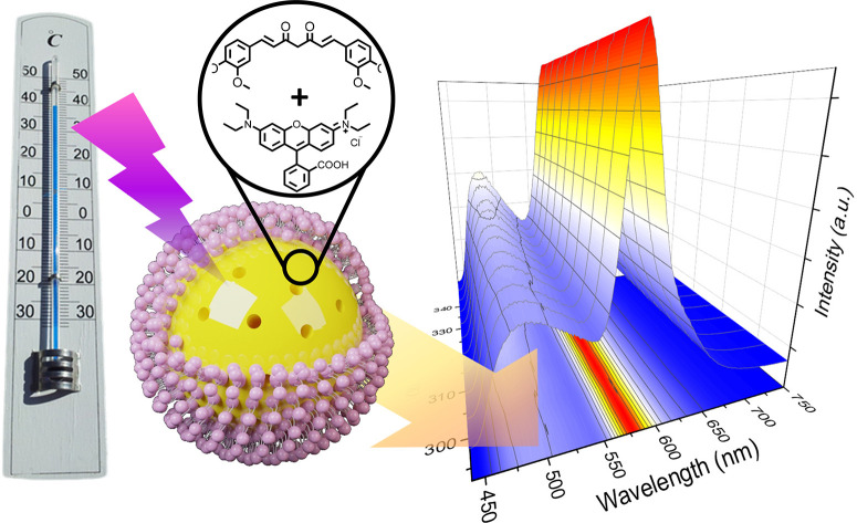
1. Introduction
Accurate temperature measurement has become increasingly important in scientific research, technological development, and various applications dependent on sensor thermometers.1 The rapid advancement of technology has created a demand for temperature sensing and measurement at the nanoscale, such as in nanoelectronics, chemical reactors, and biomedical applications.2–4 However, traditional contact thermometers, which use physical properties such as volume, electric potential, and electric conductance, are limited in their ability to measure temperature in specific environments, such as those with sub-micrometer scale, biological fluids, or fast-moving objects.5 Consequently, there has been a growing interest in noncontact and non-invasive or minimally invasive thermal sensing techniques, such as infrared light (IR) thermography, Raman spectroscopy, thermo reflectance, and luminescence thermometry.6 Of these, luminescence-based approaches have garnered significant attention due to their simplicity, high sensitivity, and exceptional spatial and temporal resolution. Recent studies have revealed that the ideal thermometer for optimal performance should possess two discriminable peaks to facilitate the development of ratiometric sensors. Such sensors capitalize on being independent of the concentration and inhomogeneity of the luminescent centers present in the material. Additionally, they help circumvent issues with alignment and optoelectronic drifts of the excitation source and detectors.7
Considerable research has been undertaken to develop and investigate innovative optical materials for their potential use as luminescence thermometers. These materials include quantum dots (QDs), polymeric and inorganic materials doped with lanthanide ions (Ln3+), organic dyes, and hybrid materials.7–9 Organic dyes have emerged as a promising alternative for ratiometric thermometry due to several advantages such as high sensitivity, low toxicity, and facile tunability of their emission properties via chemical modification. Dye-based ratiometric thermometry, an uncommon approach in the field of thermometry, relies on the ratio of intensities between specific emission bands. This innovative technique has found applications in bioimaging, food safety monitoring, and microscale temperature sensing.10–12 It's important to note that, historically, dyes have predominantly functioned as single-band thermometers.13 Despite the challenges of issues like photobleaching and environmental interference that still need resolution, the emergence of ratiometric thermometry using dyes holds great promise for advancing temperature sensing across various fields.14
Among various materials investigated for ratiometric thermometry, the utilization of dual-emitting metal–organic frameworks (MOFs) doped with fluorescent dyes has shown promising outcomes. The integration of dyes within host matrices such as MOFs present a pivotal enhancement, offering a shield against photobleaching and environmental perturbations. These ratiometric dual-emitting MOF@dye systems present an adaptable operational range and enhanced sensitivity, rendering them suitable for a spectrum of temperature sensing applications.5,15–17 It's noteworthy to clarify that within this approach, the MOFs can serve as a host material contributing to one of the emission peaks,18 or alternatively, two distinct dyes can be embedded within a non-luminescent material.15 Despite these advantages, MOFs face challenges such as inherent instability and complexities in scalable production. Furthermore, the biocompatibility and degradation behavior of these materials are crucial, particularly for biomedical uses. As a result, periodic mesoporous organosilicas (PMOs) have emerged as an attractive alternative material for thermometry platforms. Periodic mesoporous organosilicas (PMOs) are a class of highly ordered porous materials first reported in 1999.19–21 PMOs are synthesized by the self-assembly of organoalkoxysilanes under mild conditions in the presence of surfactants or block copolymers. The resulting materials have mesoporous structures with uniform pore sizes, high surface areas, and tunable functionalities. Compared to traditional silica-based materials, PMOs exhibit superior stability, high thermal and chemical resistance, and low toxicity, making them attractive candidates for various applications in catalysis, drug delivery, imaging, and sensing.22
In this study, we investigate the potential of PMOs and dyes as a ratiometric thermometry system that offers improved stability, sensitivity, and biocompatibility. Curcumin is a natural polyphenol and a well-known fluorescent dye, widely used in various biomedical and optical applications. In recent years, it has been incorporated into various matrix materials, including PMOs, due to its unique properties such as antioxidant, anti-inflammatory, and fluorescent properties.23 Therefore, curcumin functionalized PMOs (C-PMO) were developed through hydrolysis and co-condensation of curcumin-functionalized precursors with 1,2-bis(triethoxysilyl)ethane (BTESE) in the presence of cetyltrimethylammonium bromide (CTAB) surfactant. The resulting mesoporous curcumin nanoparticles (MCNs) exhibit pronounced autofluorescence and have been employed as a cargo delivery system in live-cell assays. These experiments utilize a supported lipid bilayer (SLB) to seal the pores, enabling the precise release of RhB into HeLa cells as a model cargo. Motivated by the capabilities of this C-PMO@RhB@LB system, we have adopted this composite for use as a ratiometric dual-emitting thermometer. Furthermore, we have introduced a novel curcumin-pyrazole functionalized precursor, leading to the creation of a modified curcumin-PMO (CP-PMO) system. This system features a more structurally rigid curcumin-pyrazole linkage, enhancing its potential applications.24 The resulting PMOs showed highly temperature-dependent fluorescence properties. RhB was then encapsulated in the PMO pores to create a dual-emitting PMO@dye nanocomposite, which was further coated with a lipid bilayer (LB) to enhance biocompatibility and prevent dye leaching.25 Among the previously reported dye-incorporated luminescent composites based on MOFs, C-PMO@RhB@LB and CP-PMO@RhB@LB demonstrate a very good maximum relative sensitivity (Sr) of up to 1.69 and 2.60% K−1, respectively, within the physiological temperature range. Incorporating organic dyes into the PMO framework, as demonstrated in our work, enhances the stability of the dyes and reduces photobleaching. The novel dual-emitting PMO@dye system, especially with the addition of a lipid bilayer coating, offers a biocompatible and sensitive solution for temperature sensing. This advancement in ratiometric thermometry, leveraging the stability and biocompatibility of PMOs, represents a significant contribution to the field, particularly in terms of reliability and applicability in various environments, including biomedical settings. This study enables the combination of luminescent host materials and RhB dyes, allowing for the future development of a range of ratiometric thermometers.15
2. Experimental
2.1. Materials and instrumentation
All chemicals were purchased from Sigma Aldrich, Fluorochem, Alfa Aesar, or TCI Europe and used without further purification.
Specifically, curcumin (from curcuma longa, powder) was purchased from Sigma-Aldrich with assay (HPLC, area%) ≥65%. Dulbecco's modified Eagle's medium (DMEM), fetal bovine serum (FBS), PrestoBlue™ HS (high sensitivity) cell viability reagent, and Calcein-AM cell marker dye were purchased from ThermoFisher Scientific. Penicillin–streptomycin was purchased from Sigma-Aldrich.
A Bruker D8 Advance diffractometer operating at 40 kV/30 mA using Cu-Kα radiation (λ = 0.15418 nm) equipped with a solid-state detector was employed to collect small-angle X-ray diffraction (SAXRD) patterns. Fourier transform infrared (FT-IR) spectroscopy measurements were conducted on a Thermo Nicolet 6700 FT-IR spectrometer using a KBr beam splitter and a nitrogen-cooled MCT-A detector. Nitrogen adsorption data were acquired using a TriStar II gas analyzer at 77 K after degassing the samples under a vacuum at 393 K for 24 h. A Bruker 300 MHz AVANCE spectrometer was used for 1H NMR, with CDCl3 or DMSO-d6 as the solvents. Elemental analysis (CHNS) was conducted using the Thermo Flash 2000 elemental analyzer, and V2O5 was used as a catalyst. Transmission electron microscopy (TEM) images were captured on a JEOL JEM-2200FS transmission electron microscope operated at 200 kV and equipped with a Cs corrector. All photoluminescence measurements were performed using an Edinburgh Instruments FLSP920 UV-vis-NIR spectrometer setup. The emission signals were detected using a Hamamatsu R928P photomultiplier tube, and a 450 W xenon lamp was employed as the steady-state excitation source. Temperature-dependent luminescent measurements were carried out using the Julabo refrigerated and heating F-25 circulator, which was attached to the sample holder and has a temperature range of 293–343 K with increments of 5 K. The TeSen program was utilized to process the temperature-dependent data.26
2.2. Synthesis
2.2.1. Synthesis of 4-((1E,4Z,6E)-5-hydroxy-7-(3-methoxy-4-(((3-(triethoxysilyl) propyl) carbamoyl) oxy) phenyl)-3-oxohepta-1,4,6-trien-1-yl)-2-methoxyphenyl (3-(triethoxysilyl) propyl) carbamate (curcumin-Si, 1b)
Curcumin-Si was synthesized according to a previously reported procedure.23 In a three-necked flask, 25 mL of dry tetrahydrofuran (THF) was used to dissolve the (1E,6E)-1,7-bis (4-hydroxy-3-methoxyphenyl) hepta-1,6-diene-3,5-dione (Curcumin, 1.00 g, 2.71 mmol). Triethylamine (82.26 mg, 0.81 mmol) and (3-isocyanatopropyl) triethoxysilane (IPTES, 2.68 g, 10.84 mmol) were then added while the mixture was being stirred, and it was then refluxed for 24 hours at 358 K with an Argon flow. After cooling to room temperature, the reaction mixture was filtered and washed with ethyl acetate. Then, the filtrate was evaporated. The residue was purified by silica gel column chromatography (eluent: 65 v% ethyl acetate, 33 v% petroleum ether, 2 v% triethylamine) to give Curcumin-Si as an orange oil. The resulting product was dried for 12 hours under a high vacuum before being used. Yield: 67%. 1H NMR (300 MHz, DMSO-d6) δ 9.68 (s, 1H), 7.75 (t, 1H), 7.59 (td, 2H), 7.37–7.24 (m, 2H), 7.23–7.14 (ddd, 4H), 6.97 (d, 1H), 6.92 (d, 1H), 6.83 (dd, 2H), 6.77 (d, 1H), 6.73 (s, 1H), 3.89–3.81 (s, 6H), 3.76 (qd, 12H), 3.03 (q, 2H), 1.52 (dt, 2H), 1.17 (td, 18H), 0.66–0.53 (m, 2H).
2.2.2. Synthesis of 4,4′-((1E,1′E)-(1H-pyrazole-3,5-diyl) bis(ethene-2,1-diyl)) bis(2-methoxyphenol) (curcumin-pyrazole analog, 1c)
In the procedure used by Ahsan et al.,27 curcumin (200 mg, 0.54 mmol, 1 equiv.) and hydrazine hydrate (5 equiv.) were dissolved in glacial acetic acid (10 mL). The solvent was then removed in a vacuum after the solution had refluxed for 8 hours. The residue was washed with water after being dissolved in ethyl acetate. The organic portion was collected, dried over sodium sulfate, and concentrated in a vacuum. Column chromatography (eluent: 65 v% ethyl acetate, 33 v% petroleum ether, 2 v% triethylamine) was used to purify the crude product. Yield: 82% 1H NMR (300 MHz, DMSO-d6) δ 12.79 (s, 1H), 9.10 (s, 2H), 7.36 (d, 2H), 7.14 (d, 2H), 7.01–6.69 (m, 4H), 6.76 (s, 2H), 3.83 (s, 6H). 13C NMR (400 MHz, DMSO-d6) δ 147.88, 147.88, 146.77, 128.34, 127.70, 120.08, 115.63, 115.59, 109.46, 99.31, 55.58.
2.2.3. Synthesis of 2,2′-(((1E,1′E)-(1H-pyrazole-3,5-diyl) bis(ethene-2,1-diyl)) bis(2-methoxy-4,1-phenylene))bis(N-(3-(triethoxysilyl)propyl)acetamide) (curcumin-pyrazole-Si, 1d)
To synthesize the novel Curcumin-Pyrazole-Si linker, in the analogous method used by Datz et al.,23 in a three-necked flask, 25 mL of dry THF was used to dissolve the curcumin-pyrazole analog (1.00 g, 2.75 mmol). Triethylamine (83.48 mg, 0.83 mmol) and (3-isocyanatopropyl) triethoxysilane (IPTES, 2.72 g, 11 mmol) were then added while the mixture was being stirred, and it was then refluxed for 24 hours at 358 K with an argon flow. After cooling to room temperature, the reaction mixture was filtered and washed with ethyl acetate. Then, the filtrate was evaporated. The residue was purified by silica gel column chromatography (eluent: 65 v% ethyl acetate, 33 v% petroleum ether, 2 v% triethylamine) to give Curcumin-Si as a dark orange oil. The resulting product was dried for 12 hours under a high vacuum before being used. Yield: 61% 1H NMR (300 MHz, DMSO-d6) δ 7.43–7.02 (m, 10H), 3.99 (dq, 12H), 3.87–3.65 (m, 6H), 3.33 (s, 2H), 3.03 (q, 2H), 2.93 (d, 2H), 1.99 (s, 2H), 1.56 (dt, 2H), 1.16 (qd, 18H), 0.55 (ddd, 2H).
2.2.4. Synthesis of mesoporous curcumin-PMO (C-PMO) nanoparticles and curcumin-pyrazole PMO(CP-PMO)
Following a modified literature procedure, in a two-step sol–gel reaction, cetyl trimethyl-ammonium bromide (CTAB, 0.96 mmol, 350 mg) was dissolved in a solution of 5.83 g water in a 20 mL round bottom flask. The mixture was then stirred at 353 K for 30 min after adding of 3.63 mL of NH4OH solution (25%). 120 mg of curcumin-Si (0.137 mmol)/60 mg of curcumin-pyrazole-Si (0.52 mmol) and bis(triethoxysilyl)ethane (BTESE) in 10% : 90%/38% : 62% ratios, respectively, were mixed with 1 mL of ethanol in a vial. This precursor solution was promptly injected into the stirred aqueous surfactant solution. A yellow suspension was formed, stirring for an additional two hours at 353 K. The organic surfactant was extracted by heating the sample under reflux at 363 K for 1 hour in a solution of 2 g ammonium nitrate and 100 mL ethanol. The sample was then redispersed in ethanol, heated under reflux for 45 minutes at 363 K in a solution of 100 mL ethanol, and centrifuged for 10 minutes at 8000 rpm. It was then dried overnight in an oven at 393 K.
2.2.5. Preparation of PMO@dye
A solution of RhB in distilled water was prepared in a glass vial (Table S1, ESI†). Next, 2 mL of this solution was taken and added to a new vial containing 10 mg of dry PM O powder. The mixture was first redispersed using ultrasounds for 5 minutes and then stirred for 48 hours at room temperature and centrifuged for 10 minutes at 8000 rpm. It was then dried overnight in an oven at 353 K.
2.2.6. Preparation of PMO@dye@LB (hybrid nanocomposites with lipid bilayer)
Following the reported procedure of the preparation of the lipid bilayer around the hybrid nanocomposites,25 1,2-dioleoyl-sn-glycero-3-phosphocholine (DOPC) was utilized. 5 mg of either C-PMO@RhB or CP-PMO@RhB was dispersed in 100 μL of 3.5 mM DOPC solution in a mixture of H2O and EtOH (60/40). Then, 900 μL distilled H2O was quickly added and mixed. The addition of extra water resulted in precipitation of the lipid molecules, which were expected to cover the surface of the hybrid nanocomposite with a lipid layer. The PMO@dye@LB was purified by centrifugation and redispersion in a small amount of H2O, and this process was repeated to ensure complete purification of the material. It was then dried overnight in an oven at 353 K.
2.3. Cytotoxicity test
2.3.1. Cell cultures
For the cell viability assays, healthy normal human dermal fibroblast (NHDF) cells were cultivated using a cell growth medium solution (DMEM + 10% FBS + 1% Pen-Strep) and were subsequently seeded in 96-well plates with a seeding concentration of 5000 cells per well upon reaching 80–90% confluency during early culture passage stages (P2–P5). The cell plates were incubated for 24 hours in the dark at 37 °C and 5% CO2.
2.3.2. Cell viability assay
Cytotoxicity tests were conducted on a series of sample concentrations: 0, 0.028, 0.056, 0.278, 0.556, 1.111, 1.667, and 2.778 mg mL−1 (or 0, 0.005, 0.01, 0.05, 0.1, 0.2, 0.3, and 0.5 mg per well respectively), to evaluate the effect of the prepared materials on in vitro cultured healthy NHDF cells. The obtained results summarize the data readout from five technical replicates per tested concentration per sample.
The compatibility of each of the samples with the in vitro cultured adherent healthy NHDF cells was investigated and quantified using the PrestoBlue™ HS cell viability assay via fluorescence spectroscopy measurements with λexc = 560 nm and λem = 635 nm. The samples (as dry powders) were suspended in the cell growth medium solution to prepare the respective stock solutions. To obtain uniform dispersions and eliminate particle agglomerates, the stock solutions were vortexed for 1 minute and ultrasonicated for 10 minutes before addition/dilution in the appropriate concentration to the wells containing previously seeded and incubated cells. The cytotoxic effect of the as-prepared materials was investigated in a series of sample concentrations ranging from 0–2.778 mg mL−1, tested on five technical replicates per concentration. Upon sample addition, the cell plates were incubated for 24 hours in the dark at 37 °C and 5% CO2. The following day, 20 μL of the PrestoBlue™ HS reagent was added to all wells and the plates were again incubated in the dark for 4 hours at 37 °C and 5% CO2. Negative controls contained seeded cells, cell growth medium, and PrestoBlue™ HS cell viability reagent, while positive controls or PB-blanks contained PrestoBlue™ HS cell viability reagent and cell growth medium solution. The fluorescence emission of the cell plates was measured on a Tecan spectrophotometer equipped with a microplate reader.
The data readout is normalized with respect to the averaged negative controls in the following way: where FI stands for fluorescence emission intensity at 635 nm; a technical replicate is a technically repeated sample concentration containing seeded cells, cell growth medium solution, and PrestoBlue™ HS cell viability reagent; (negative) controls represent plate wells containing seeded cells, cell growth medium solution, and PrestoBlue™ HS cell viability reagent; and PB-blanks represent plate wells containing cell growth medium solution and PrestoBlue™ HS cell viability reagent; all equalized to the same final volume per well by cell growth medium solution.
Simultaneously, parallel technical replicates were prepared for the widefield fluorescence microscopy imaging under identical treatment, replacing the PrestoBlue™ HS cell viability reagent with Calcein-AM fluorescent cell marker dye with a concentration of 0.3 μL per well or a final plate well concentration of 1.5 μM. After dye addition, the cell plates were incubated for 20 minutes in the dark at 37 °C and 5% CO2. Cell visualization was performed using a green fluorescent protein (GFP) long-pass filter on a Nikon Ti widefield microscope transmitting all emitted wavelengths ≥500 nm, under excitation of 470 nm.
3. Results and discussion
3.1. Structural characteristics of PMO@dye@LB
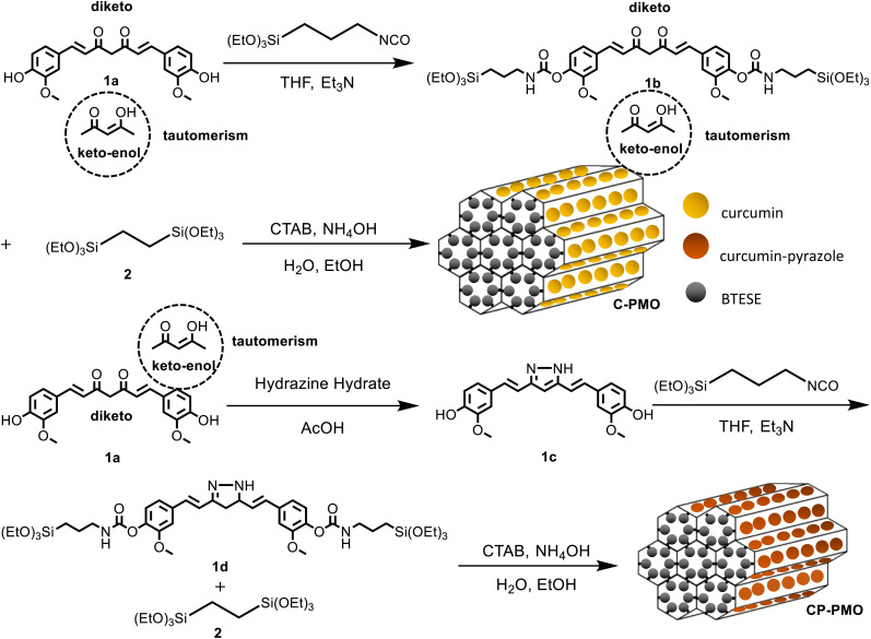
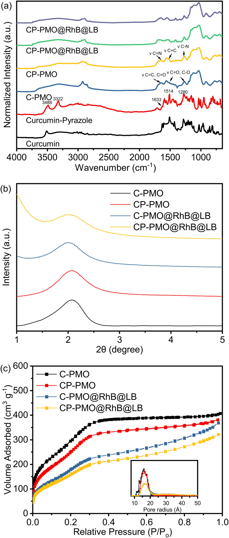
Precursor preparation was the first step in the development of the nanomaterials. Compound curcumin-Si (1b) had been synthesized utilizing IPTES for silylation on curcumin (1a). Curcumin (1a) was converted into curcumin-Pyrazole (1c) analog by the addition of hydrazine, then curcumin-pyrazole-Si (1d) was produced using further reacting compound curcumin-pyrazole (1c) with IPTES (Scheme 1). Using a co-condensation technique with BTESE, curcumin-Si or curcumin-pyrazole-Si was finally covalently incorporated into the PMO frameworks. According to earlier research by Joseph et al. and Muddassar et al. on the vibrational spectra of curcumin and curcumin-pyrazole, respectively,28,29 FT-IR spectra were used to determine the synthesis of 1c and the formation of C-PMO and CP-PMO (Fig. 1a). Firstly, when compared to 1a, several typical variations in the 1c spectrum may be seen. The overlap of C–OH and C–NH bond vibration may cause a strong, and broad peak at 3488/3322 cm−1. For 1c, because of the C N stretching frequencies, a band can be seen at 1633 cm−1.
Scheme 1. Schematic illustration of the preparation of the C-PMO and CP-PMO and representation of the diketo/keto–enol tautomerism of curcumin.
Fig. 1. (a) FTIR spectra of PMO@RhB@LB; (b) PXRD patterns of PMOs@RhB@LB; (c) N2 adsorption–desorption isotherms and pore size distributions of PMO@RhB@LB.
Moreover, stretching vibrations of the C C bonds were represented by a strong, intense band at 1514 cm−1, while a second, similar band at 1280 cm−1 represented the C–N bond. Secondly, a new band at 1041 cm−1 represented the stretching vibrations of the Si–O–Si frameworks. Thirdly, the characteristic absorption peaks of the 1a (νC C,C O = 1650 cm−1, νC O,C–O = 1511, 1272 cm−1) and 1c moieties (νC N = 1650 cm−1, νC C = 1513 cm−1, νC–N = 1276 cm−1) remained after removal of the surfactant (CTAB), with showing the stable immobilization of curcumin and curcumin-pyrazole units into the silica framework. The FTIR spectra of the samples containing RhB showed negligible variations, and the distinctive absorption peaks of RhB could not be identified in the spectra.
This is because the mass fraction of RhB in the material is considerably lower than that of the matrix materials. As a result, the IR absorptions of RhB have been concealed by the matrix materials, particularly when the characteristic absorption peaks are close to those of the matrix.30
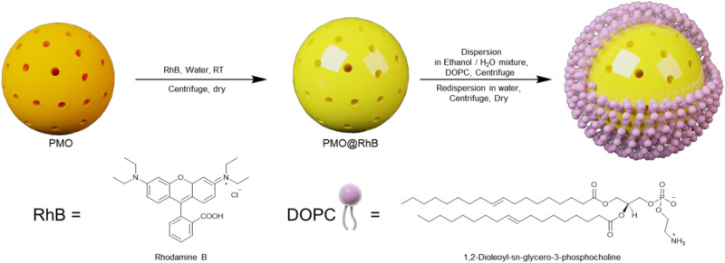
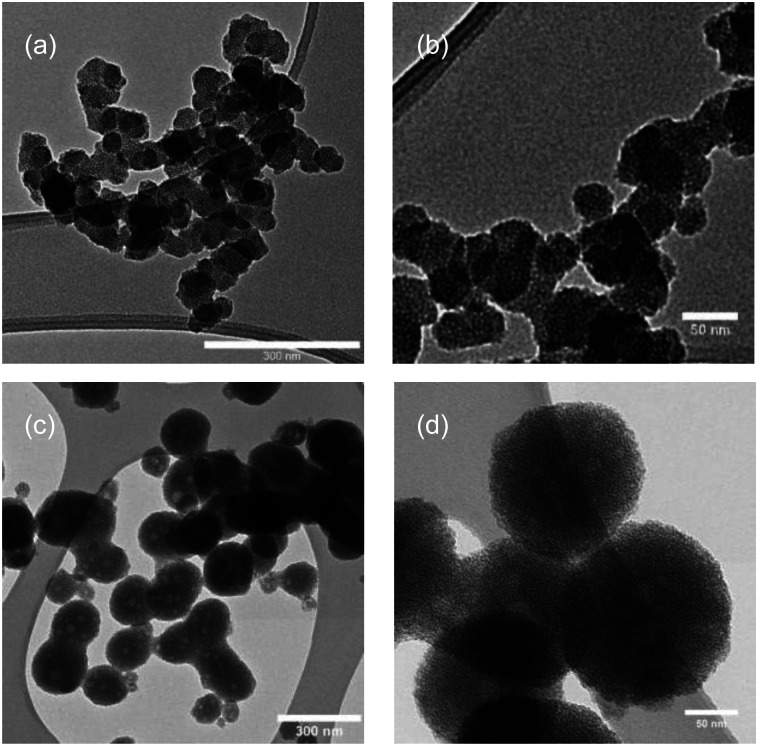
SAXRD and N2 adsorption measurements were carried out to investigate the structural response of the materials to functionalization. The SAXRD profiles of the surfactant-free C-PMO and CP-PMO were shown in Fig. 1b. The diffraction peak was observed at around 2θ = 2° for these two samples, indicative of a mesoscopically ordered structure.31Fig. 1c depicts the N2 adsorption–desorption isotherm of these two materials. By comparing the isotherm of C-PMO with that of CP-PMO, it was observed that the shape remained the same. Both materials had the type IV isotherm, indicating that the ordered mesoporous structure had successfully been formed.32 Brunauer–Emmett–Teller (BET) surface area for C-PMO and CP-PMO were 1254 m2 g−1 and 1149 m2 g−1, respectively, and the total pore volumes were 0.63 cm3 g−1 and 0.59 cm3 g−1, respectively. In addition, the pore size of PMOs calculated using the non-local density functional theory (NLDFT) method were both 3.2 nm (Table 1). Therefore, the resulting material's mesostructure is coincident with the results of XRD patterns. Additionally, the confirmation of a lipid bilayer on the surface of PMO particles was carried out using BET analysis. After the introduction of dyes inside the pores of PMO, the pristine C-PMO and CP-PMO particles were coated with a lipid bilayer (Scheme 2), resulting in a reduction in surface area to 901 and 979 m2 g−1, respectively. The observed reduction in surface area implies that the lipid bilayer, along with the incorporated dyes, partially obstructs the pores of the PMO particles, while also wrapping around the particle structure. To confirm the feasibility of the sensing application, we compared the particle morphologies of these two materials by utilizing TEM. As shown in Fig. 2b and d, both possess representative spheres with an average diameter of 69 ± 13 and 153 ± 11 nm, respectively. Regarding the TEM observations, we recognize the noted differences in particle size and aggregation between CP-PMO and C-PMO. This discrepancy can indeed be attributed to the differing chemical interactions and steric hindrance presented by the pyrazole moiety in CP-PMO, which may affect particle nucleation and growth. Besides higher concentration in precursors ratio of CP-PMO, the distinct interactions of functional groups in C-PMO and CP-PMO with solvents, surfactant can modulate the kinetics of polymerization or condensation reactions, impacting particle nucleation and growth.33
Textural properties of prepared C-PMO and CP-PMO.
| Material | S BET (m2 g−1) | Pore diametera (nm) | Total pore volume (cm3 g−1) |
|---|---|---|---|
| C-PMO | 1254 | 3.2 | 0.63 |
| CP-PMO | 1149 | 3.2 | 0.59 |
| C-PMO@RhB4@LB | 721 | 3.2 | 0.33 |
| CP-PMO@RhB1@LB | 806 | 3.1 | 0.37 |
Calculated from NLDFT, N2 at 77 K, using the kernel of silica cylindrical pore, adsorption branch.
Scheme 2. Schematic illustration of the preparation of the PMO@RhB@LB.
Fig. 2. TEM images of (a) and (b) C-PMO and (c) and (d) CP-PMO.
3.2. Temperature-related fluorescence of PMO@dye@LB
3.2.1. Fluorescence of the prepared PMO@dye@LB
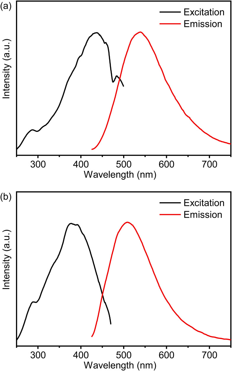
Fig. 3 presents the solid-state excitation and emission spectra of PMOs at room temperature. The excitation bands of the materials are broad, spanning from 250 nm to over 480 nm. All prepared materials exhibit strong visible emission, which can be observed with the naked eye (Fig. S3a, ESI†). The photoluminescence properties of the C-PMO and CP-PMO material were measured at room temperature, and the emission band was acquired by exciting at 417 nm. The C-PMO material emits over a broad range of wavelengths, ranging from 430 to 750 nm, with a peak maximum at 539 nm. The emission is related to the π–π* electron transition of the curcumin linker.23 Compared similarly, the CP-PMO material shows a slight blue-shifted spectrum and exhibits a broad emission band ranging from 430 to 750 nm, with a peak maximum at 509 nm, which may be attributed to the change in the rigidity of the curcumin-pyrazole linker. The fluorescence emission spectrum of RhB in water exhibits a prominent emission peak at approximately 641 nm when excited at 385 nm, as shown in Fig. S4a (ESI†). Additionally, its UV-Vis absorption spectrum shows broad absorbance in the range of 450–600 nm (Fig. S4b, ESI†). Notably, there is a spectral overlap between the emission spectrum of PMOs and the absorption spectrum of RhB, as depicted in Fig. S4b (ESI†). This indicates the possibility of efficient energy transfer from PMO to RhB upon excitation at 417 nm. Further insight is offered through Fig. S5 (ESI†), which elucidates the luminescence decay profiles of the individual emissions within the PMOs.34 It is notable that the observed decay times for the curcumin functionalized PMOs appear to be extremely prolonged, comparing with existing literature.35 The photoluminescence quantum yield of curcumin exhibits low values across various solvents, with a pronounced decrease observed in aqueous environments. Consequently, the fluorescence lifetime of curcumin in liquid phase at ambient temperature is notably short, typically less than 1 nanosecond.36 The shortened fluorescence lifetime of such dyes in the picosecond range is hypothesized to stem from internal barrierless rotation within the excited state.37 Given that rotational motions around double bonds are known to decrease fluorescence lifetime, it follows that restricting such rotations—by embedding the fluorophores within a rigid matrix (PMOs), reducing ambient temperature, or stabilizing the molecule's flexible segments—would mitigate nonradiative decay channels, thereby enhancing both fluorescence intensity and lifetime.38,39 These profiles effectively demonstrate a decrease in decay time of PMO's emission as the quantity of added RhB solution increases.
Fig. 3. Combined RT excitation–emission spectrum of the (a) C-PMO and (b) CP-PMO in water (excited at 417 nm and observed at 525 nm).
To enhance the performance of PMO@dye@LB, various composites of PMO@dye@LB with differing dye concentrations were synthesized, adhering to the ratios delineated in Table S1 (ESI†). Fig. S6 and S7 (ESI†) present the emission spectra of PMO@dye@LB with different dye contents dispersed in water at room temperature. As anticipated, the PMO@dye@LB composite exhibits simultaneous emission profiles of the rigidified linker and RhB under the same conditions as PMO. The emission peak profile of RhB in PMOs (596 nm) is blue-shifted compared to that of the RhB water solution (641 nm) and is attributed to pore confinement of RhB within PMO due to strong interaction between curcumin/curcumin-pyrazole linker of PMO and RhB dye.5 It also suggests that RhB is uniformly accommodated as isolated molecules in the pores of PMO, avoiding the formation of excimers or aggregates in the solid phase.17 By decreasing the RhB content in the pores of the host framework, the emission color of PMO@dye@LB can be tuned, with the color depending on the combination of emissions from PMO and RhB, as well as the energy transfer process between the two. With decreasing RhB content, the orange emission (596 nm) of RhB is attenuated while the emission of PMOs is enhanced, resulting in a color change from orange to yellow. The observed blue shift in the emission peak of RhB with decreasing dye concentration is related to the confinement effect within the PMO's porous structure. This effect limits the RhB molecules' spatial orientation and their potential to aggregate. As RhB concentration decreases, spatial confinement becomes more significant, leading to an increased presence of isolated RhB molecules. These isolated molecules have emission characteristics distinct from those in aggregated states, causing the noted blue shift.40 The CIE chromaticity diagram for PMO@dye@LB was depicted to show the color changes from orange to red (Fig. S8, ESI†).
3.2.2. Ratiometric temperature sensing properties of PMO@dye@LB
To assess the potential of PMO@dye@LB as a ratiometric thermometer, a detailed investigation was conducted on its temperature-dependent photoluminescent properties. Initially, the host PMOs were excited at a wavelength of 417 nm, and the emission spectra were analyzed across a temperature range of 293 to 323 K (refer to Fig. S9, ESI†). A notable decrease in luminescence was observed for both the curcumin and curcumin-pyrazole linkers with increasing temperature, showing reductions of 0.74% and 1.29% per K, respectively (as depicted in Fig. S9, ESI†). This decline in fluorescence can be attributed to the thermal activation of nonradiative decay pathways and relaxation.18 Given the complexity of these processes and their dependence on the molecular structure and environment, pointing out the exact pathways without extensive additional studies can be challenging. Our current analysis was based on observed trends consistent with the general understanding of thermally induced nonradiative decay in similar systems. Additionally, Fig. S10 (ESI†) presents the luminescence decay profiles for these emissions at varying temperatures, highlighting their temperature-responsive characteristics. The luminescence lifetime, which signifies the average duration of the excited state, is observed to decrease with rising temperatures due to the increased rate of nonradiative decay.
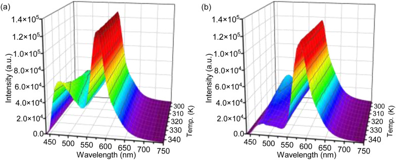
Subsequently, the temperature-dependent emission spectra of PMO@dye@LB were examined under identical conditions, extending the temperature range to 343 K (as shown in Fig. S3b, S11 and S12, ESI†). The intricate temperature-dependent changes in various emission bands are succinctly quantified by stating percentage changes per Kelvin (% K−1). The intensity of the curcumin linker in C-PMO@RhB@LB was found to decrease by 0.43% per Kelvin over the range of 293 to 343 K (Fig. S11, ESI†), a rate significantly higher than that in pristine C-PMO (0.74% K−1). Conversely, the peak intensity of the curcumin-pyrazole linker in CP-PMO@RhB@LB displayed a decrease of 1.18% K−1 (Fig. S12, ESI†), marginally lower than its rate in CP-PMO (1.29% K−1). Detailed analysis of these materials and their CIE coordinates at different temperatures is presented in Fig. S13 (ESI†). Within the C-PMO framework, the emission intensity of the curcumin linker remains stable with temperature increase, indicating minimal impact from thermal activation of nonradiative decay or relaxation processes. However, Fig. S11 (ESI†) demonstrates that the luminescence of RhB is more susceptible to temperature-induced changes compared to the curcumin linker. It is acknowledged that rhodamine B (RhB) is highly sensitive to temperature variations.15 In contrast, the emission from the curcumin-pyrazole linker in CP-PMO@RhB@LB shows a marked intensity decline with increasing temperature, even more pronounced than the decrease observed for RhB (Fig. S12, ESI†). This suggests that the interaction between the CP-PMO host and the dye enhances the temperature sensitivity of the CP-PMO compared to RhB. Based on their clear intensity changing trends between curcumin PMO and RhB, we specifically focused on the spectra of C-PMO@RhB4@LB and CP-PMO@RhB1@LB. Fig. 4 illustrates the temperature dependence by displaying the normalized intensities of their corresponding emissions. The PMO@dye composites effectively retain the emissions of both RhB and organic linkers, which exhibit distinct thermal dependencies. As a result, the intensity ratio between these emissions is highly sensitive to temperature, providing a self-calibrated thermometric parameter for accurate temperature sensing.
Fig. 4. Temperature-dependent normalized emission spectra of (a) C-PMO@RhB4@LB and (b) CP-PMO@RhB1@LB dispersed in water recorded from 293.15 to 343.15 K, when excited at 417 nm.
Ratiometric luminescence temperature measurement involves utilizing the emission intensities of two distinct luminescence centers. This measurement technique utilizes an intensity ratio parameter (Δ = Ipro/Iref), which represents the emission intensity of the probe (Ipro) relative to that of the reference (Iref) in the PMO@RhB@LB system. The temperature dependence of the parameter Δ was analyzed using the well-known Mott–Seitz model,41,42 which takes into account the interplay between radiative and nonradiative decay processes of each emitting center. In summary, the temperature dependence of Δ can be described by eqn (1).
 |
1 |
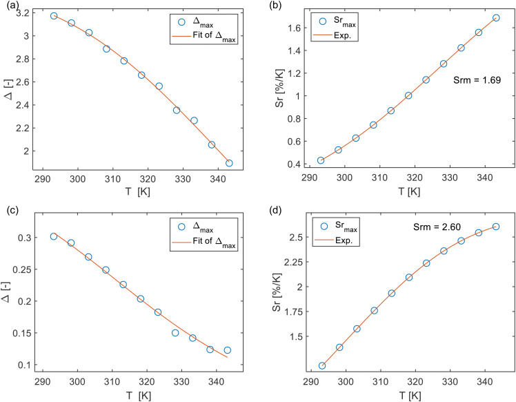
where Δ0 is the ratiometric parameter Δ at T = 0 K, the parameter α represents the ratio between the nonradiative and radiative probabilities of the deactivation channel. kB refers to the Boltzmann constant, and ΔE represents the activation energy of the nonradiative process (thermal quenching). The differential temperature sensitivity of C-PMO and RhB leads us to designate the emission intensity of C-PMO as Iref, reflecting its lower temperature responsiveness compared to RhB. Conversely, due to CP-PMO's heightened temperature sensitivity, surpassing that of RhB, the emission intensity of CP-PMO is denoted as Ipro. In accordance with eqn (1), the experimental values of the parameters Δ for C-PMO@RhB4@LB and CP-PMO@RhB1@LB can be well fitted using the eqn (1) with the correlation coefficient (R2) of 0.997 and 0.992, respectively (Table S2, ESI†).
The results obtained can properly be described using the single barrier model of eqn (1), indicating the presence of a single energy barrier for thermally induced non-radiative decay in both compounds. The temperature calibration curves (depicted as red solid lines) in Fig. 5a and c demonstrate the nature of the thermally activated channel in C-PMO@RhB4@LB and CP-PMO@RhB1@LB, respectively. The fitted α value for CP-PMO@RhB1@LB is higher than that of C-PMO@RhB4@LB, indicating a stronger nonradiative deactivation in the latter composite. Of particular importance, the S-shaped fitting of the calibration curves yielded two activation energies: ΔEC-PMO = 3065.4 cm−1 for C-PMO@RhB4@LB and ΔECP-PMO = 2936.5 cm−1 for CP-PMO@RhB1@LB. A smaller activation energy typically indicates that the temperature-dependent process, such as a nonradiative decay pathway or an energy transfer mechanism, occurs more readily with changes in temperature. This means that the transition between different emitting states or energy levels within the material happens more easily, leading to a more pronounced change in the intensity or ratio of emission bands used for temperature sensing.18 In conclusion, it indicates that the curcumin-pyrazole linker is more sensitive to temperature changes compared to curcumin linker, even higher than RhB in CP-PMO@RhB@LB. These findings align with the earlier assessment of the temperature dependence of the luminescent intensity and lifetime.
Fig. 5. (a) and (c) Delta calibration curve for C-PMO@RhB4@LB and CP-PMO@RhB4@LB when eqn (1) is employed. The points show the experimental Δ parameters and the solid line shows the best fit of experimental points. (b) and (d) Sr values at varying temperatures (293–343 K). The data is obtained based on the peak maxima.
The relative thermal sensitivity (Sr) is a commonly used figure of merit to evaluate and compare the performance of different dual-emitting thermometers.42 By comparing the Sr values of various thermometers, we can assess their effectiveness in accurately measuring temperature variations. Higher Sr values indicate a higher sensitivity to temperature changes, making a thermometer more suitable for precise temperature measurements. It can be defined as
 |
2 |
where Δ is the ratiometric parameter of our composites and T is the absolute temperature. In accordance with the aforementioned definition, the relative thermal sensitivity (Sr) values of C-PMO@RhB4@LB and CP-PMO@RhB1@LB were calculated and presented in Fig. 5. It can be observed that within the range of 293 to 343 K, the maximum Sr values for C-PMO@RhB4@LB and CP-PMO@RhB1@LB were determined to be 1.69% K−1 and 2.60% K−1, respectively. It is evident that the composite CP-PMO@RhB1@LB exhibit superior relative sensitivities compared to its respective counterpart, C-PMO@RhB4@LB. The enhanced sensitivity of CP-PMO@RhB1@LB can be attributed to the stronger interaction and reduced nonradiative decays between RhB and the CP-PMO framework. Since it is a novel concept to utilize PMO@dye composite as ratiometric thermometry system in biomedical applications, there are few reported analogous compounds for comparison. Within the spectrum of dye-embedded MOF-derived luminescent materials, our studies reveal that C-PMO@RhB4@LB and CP-PMO@RhB1@LB stand out for their good maximum relative sensitivity (Srm) within the physiological temperature range, as detailed in Table S3 (ESI†). Notably, these composites exhibit enhanced sensitivities at elevated temperatures, underscoring their promising applicability for temperature sensing in higher temperature environments. Consequently, the RhB-doped PMO composites emerge as candidates for precise temperature monitoring applications under such conditions.
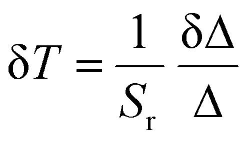
The temperature resolution (δT) is a crucial parameter for evaluating luminescent thermometers and can be defined as follows:43
 |
3 |
where δΔ/Δ is the relative standard deviation of the Δ.44 The temperature uncertainty (δT) of the composites were calculated using eqn (3), and the results indicate that it remains below 0.07 K across the entire temperature range under investigation (Fig. S14, ESI†).
To assess the reversibility of the luminescent thermometer, a series of temperature-dependent emission measurements were conducted over four consecutive cycles within the temperature range of 293 to 343 K. The results demonstrate that the emission intensity ratio remains nearly constant at various temperatures throughout each cycle (Fig. S15, ESI†), indicating the excellent reversibility of the system.3
3.3. PrestoBlue™ HS cell viability assay conducted on NHDF cell line
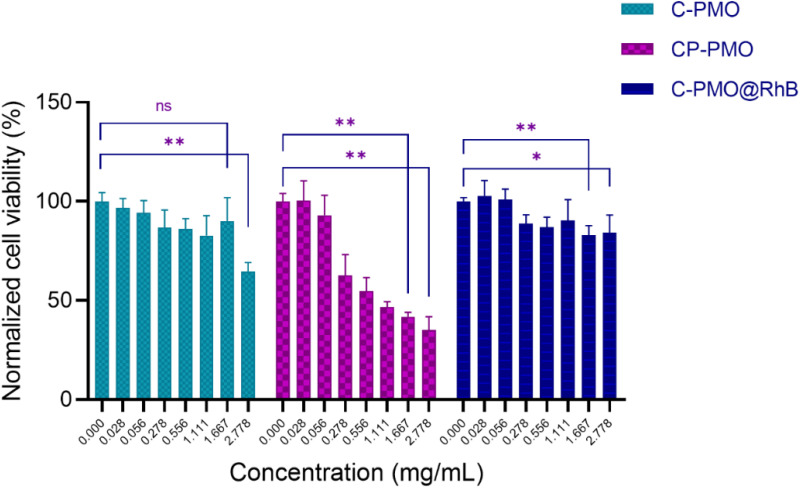
From the obtained graph (Fig. 6), it can be observed that overall, all three materials generally manifest a slight cytotoxic effect across the investigated concentration range. The C-PMO and the C-PMO@RhB@LB materials are negligibly toxic to the NHDF cells in the entire investigated concentration range, especially in the first portion of the range (up to a concentration of 1.667 mg mL−1) which includes and coincides with the targeted values that may be readily and successfully exploited for the thermometric measurements (proposed in the literature as a maximum of 1 mg mL−1). Increasing the concentration of C-PMO from 1.667 mg mL−1 to 2.778 mg mL−1 decreases the NHDF cell viability from ∼88 to 60%, therefore it can be concluded that C-PMO is significantly toxic to the cells only at the highest tested concentration, which exceeds practical concentration limits for thermometry applications. However, for the C-PMO@RhB@LB material, even at the highest tested concentration the cell viability is determined to be ∼80%, displaying that compared to the C-PMO, the C-PMO@RhB@LB material maintains non-toxicity in a wider range, indicating that incorporation of the lipid bilayer has a favorable influence contributing to the enhanced compatibility of the material with the healthy human fibroblast cells.
Fig. 6. Cumulative grouped bar graph (mean + SD) of cytotoxicity test results obtained for the three tested materials. A nonparametric statistical analysis was conducted, employing the Mann–Whitney–Wilcoxon test to investigate for significant differences between the control median and any other concentration group median of a tested sample, where * represents p < 0.05 and ** represents p < 0.01, and ns stands for statistically non-significant differences.
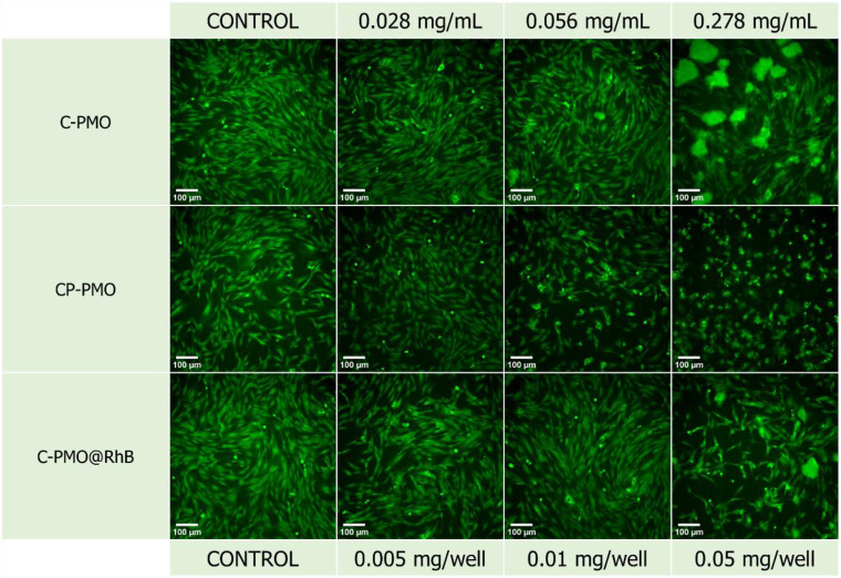
The widefield microscopy images (Fig. 7 and Fig. S18, ESI†) also show the increasing aggregation of the sample in the same range of increasing sample concentration, making the spindle-shaped morphology of the NHDF cells less visible to entirely undetectable at the highest tested concentration because of the topical fluorescence emission from the aggregated particles themselves and not because of complete cell death (Fig. S18, ESI†). Because the particles fluoresce inherently, their emission is also detected on the widefield microscope, while the excitation wavelength of the cell labeling dye and the PMOs coincide. Since the stain emission readout for the cytotoxicity and microscopy replicates is collected at different emission wavelengths (635 nm and ≥500 nm respectively) it can be concluded that there are still viable cells in the wells treated with the highest concentration even though they are not visually detectable in the microscopy images since the aggregations obstruct the visual field of the microscope. This can be attributed to the relatively high concentrations of sample added in a suspension to the seeded cells. For the CP-PMO material, the toxic effect is slightly more pronounced with cell viability decreasing from ∼60 to ∼30% in the concentration range from 0.278 to 2.778 mg mL−1, resulting overall in a very steep toxicity slope at the higher portion of the concentration range. The fluorescence microscopy images show less aggregation for the CP-PMO sample as compared to the other two samples at the same concentrations, making it evident that the cell viability does decrease going from 0.278 to 2.778 mg mL−1, depicted visually too (Fig. S18, ESI†). To conclude, comparatively, the C-PMO@RhB@LB material is the least toxic among the three tested, with cell viability decreasing down to ∼80% for the highest tested concentration of 2.778 mg mL−1 even though some sample aggregation is evident at higher concentrations. This highlights the suitability and beneficial compatibility of this material to be exploited successfully in thermometry applications in optimal doses. The statistically significant differences between the control mean and the means of the other columns (shown on the bar graph) could be due to the notable aggregates with different dimensions present in the plate wells at much higher concentrations of the materials. Additionally, it's worth noting the comparative lower toxicity and higher applicability of the C-PMO@RhB@LB system in bioapplications, highlighting its potential as a safer alternative for biomedical use. While acknowledging that the CP-PMO@RhB@LB system remains a viable option for other applications, the selection between these systems should be guided by the specific requirements of the application in question, balancing factors such as toxicity, biocompatibility, and functional performance.
Fig. 7. Fluorescence microscopy images of the technical replicates with stained NHDF cells for the three samples (C-PMO, CP-PMO, C-PMO@RhB4@LB). Calcein-AM was used as the cell stain at a final well concentration of 1.5 μM. All scale bars are set to 100 μm.
Here, we underscore the advantages of utilizing RhB dye-incorporated curcumin PMOs for ratiometric dual-emitting thermometry. Our selection of the soaking post-functionalization technique underscores its simplicity, versatility, and adaptability for optimized dye integration and a broader dye selection, aligning well with diverse application needs and scalability for mass production. We acknowledge the existence of an alternative synthetic strategy, where dyes are integrated during the PMO synthesis, potentially offering more uniform dye distribution.45 However, this alternative could introduce challenges, such as a narrower dye selection and increased synthesis complexity. It is crucial to note that our investigation was deliberately focused on the post-functionalization approach, without exploring the comparative merits of the in-synthesis dye incorporation, hence a direct comparison remains outside the scope of this study.
Furthermore, despite the excitation and emission wavelengths' limitation to the visible range potentially limiting some biomedical applications, the unique properties of these materials open up possibilities, particularly in precise cellular temperature measurements within laboratory settings. The ability to accurately track and comprehend intracellular temperature fluctuations is vital for delving into cellular functions, metabolic activities, and reactions to external stimuli. Employing ratiometric dual-emitting thermometry facilitated by RhB dye-incorporated curcumin PMOs offers a novel way for exploring cellular temperature dynamics. This information can contribute to advancements in cellular biology, drug delivery systems, temperature imaging, and the development of targeted therapies.46
4. Conclusions
In conclusion, our research has successfully developed two novel ratiometric thermometers: curcumin-functionalized PMOs (C-PMO) and curcumin-pyrazole-functionalized PMOs (CP-PMO), both incorporating RhB as a model dye. The C-PMO serves as an excellent host matrix for RhB, ensuring efficient encapsulation and stability of the dye within its structure. This combination results in dual-emitting properties, leveraging the fluorescence emissions of both the curcumin linker and RhB for a temperature-dependent response. The C-PMO@RhB demonstrates a higher relative sensitivity compared to previous thermometers within the physiological temperature range and exhibits the least toxicity among the materials tested, making it particularly suitable for biomedical applications. Furthermore, the CP-PMO represents an advanced step in this research, introducing a modified curcumin-pyrazole linker. This modification enhances the temperature sensitivity of the composite, as indicated by its good maximum relative sensitivity. The incorporation of the curcumin-pyrazole linker in CP-PMO not only contributes to a diverse emission profile but also suggests potential for even broader applications due to its enhanced thermal response. The synthesis of both C-PMO and CP-PMO, and their incorporation with RhB, mark an advancement in the field of luminescent thermometry. These dual-emitting ratiometric thermometers offer innovative and promising approaches for accurate temperature sensing. The successful demonstration of these composites underscores their potential for practical applications and sets a precedent for future explorations in luminescent temperature sensing technologies.
Conflicts of interest
There are no conflicts to declare.
Supplementary Material
Acknowledgments
C. H. L. gratefully acknowledges the financial support from the China Scholarship Council (201908110280). P. V. D. V. acknowledges Hercules Project AUGE/17/07 for the UV VIS DRS spectrometer and UGent BASBOF BOF20/BAS/015 for the powder X-Ray Diffractometer. A. M. K. and S. P. acknowledge that this work is part of a project that has received funding from the European Research Council (ERC) under the European Union's Horizon 2020 research and innovation programme (Grant agreement No. 945945). The authors thank Prof. Rik Van Deun for access to the spectrofluorometer in his lab. The authors thank Katrien Haustraete for STEM-EDX measurements.
Electronic supplementary information (ESI) available. See DOI: https://doi.org/10.1039/d3tc04416e
References
- Wang X. D. Wolfbeis O. S. Meier R. J. Chem. Soc. Rev. 2013;42:7834–7869. doi: 10.1039/C3CS60102A. [DOI] [PubMed] [Google Scholar]
- Bradley D. I. George R. E. Gunnarsson D. Haley R. P. Heikkinen H. Pashkin Y. A. Penttila J. Prance J. R. Prunnila M. Roschier L. Sarsby M. Nat. Commun. 2016;7:10455. doi: 10.1038/ncomms10455. [DOI] [PMC free article] [PubMed] [Google Scholar]
- Kaczmarek A. M. Jena H. S. Krishnaraj C. Rijckaert H. Veerapandian S. K. P. Meijerink A. Van Der Voort P. Angew. Chem., Int. Ed. 2021;60:3727–3736. doi: 10.1002/anie.202013377. [DOI] [PubMed] [Google Scholar]
- Bednarkiewicz A. Marciniak L. Carlos L. D. Jaque D. Nanoscale. 2020;12:14405–14421. doi: 10.1039/D0NR03568H. [DOI] [PubMed] [Google Scholar]
- Zhou Y. Zhang D. Zeng J. Gan N. Cuan J. Talanta. 2018;181:410–415. doi: 10.1016/j.talanta.2018.01.024. [DOI] [PubMed] [Google Scholar]
- Suo H. Zhao X. Zhang Z. Wang Y. Sun J. Jin M. Guo C. Laser Photonics Rev. 2021;15:2000319. doi: 10.1002/lpor.202000319. [DOI] [Google Scholar]
- Kaczmarek A. M. Liu Y. Y. Kaczmarek M. K. Liu H. Artizzu F. Carlos L. D. Van Der Voort P. Angew. Chem., Int. Ed. 2020;59:1932–1940. doi: 10.1002/anie.201913983. [DOI] [PubMed] [Google Scholar]
- Cheng Y. Gao Y. Lin H. Huang F. Wang Y. S. J. Mater. Chem. C. 2018;6:7462–7478. doi: 10.1039/C8TC02401D. [DOI] [Google Scholar]
- Brites C. D. S. Lima P. P. Silva N. J. O. Millan A. Amaral V. S. Palacio F. Carlos L. D. New J. Chem. 2011;35:1177–1183. doi: 10.1039/C0NJ01010C. [DOI] [Google Scholar]
- Liu G. Liu D. Han X. Sheng X. Xu Z. Liu S. H. Zeng L. Yin J. Talanta. 2017;170:406–412. doi: 10.1016/j.talanta.2017.04.038. [DOI] [PubMed] [Google Scholar]
- Zeng H. L. Zhu Y. L. Ma L. L. Xia X. H. Li Y. H. Ren Y. Zhao W. Y. Yang H. Deng R. J. Dyes Pigm. 2019;164:35–42. doi: 10.1016/j.dyepig.2019.01.005. [DOI] [Google Scholar]
- Wu Y. Liu J. Ma J. Liu Y. Wang Y. Wu D. ACS Appl. Mater. Interfaces. 2016;8:14396–14405. doi: 10.1021/acsami.6b03366. [DOI] [PubMed] [Google Scholar]
- Brites C. D. S. Lima P. P. Silva N. J. O. Millan A. Amaral V. S. Palacio F. Carlos L. D. Nanoscale. 2012;4:4799–4829. doi: 10.1039/C2NR30663H. [DOI] [PubMed] [Google Scholar]
- Chi W. J. Yin W. T. Qi Q. K. Qiao Q. L. Lin Y. Y. Zhu Z. H. Vijayan S. Hashimoto M. Udayakumar G. Xu Z. C. Liu X. G. Mater. Chem. Front. 2017;1:2383–2390. doi: 10.1039/C7QM00345E. [DOI] [Google Scholar]
- Peng M. Kaczmarek A. M. Van Hecke K. ACS Appl. Mater. Interfaces. 2022;14:14367–14379. doi: 10.1021/acsami.2c01332. [DOI] [PubMed] [Google Scholar]
- Gong M. Y. Li Z. J. Xiang W. Q. Xia T. F. Zhao D. J. Solid State Chem. 2022;311:123147. doi: 10.1016/j.jssc.2022.123147. [DOI] [Google Scholar]
- Zhao D. Yue D. Jiang K. Cui Y. Zhang Q. Yang Y. Qian G. J. Mater. Chem. C. 2017;5:1607–1613. doi: 10.1039/C6TC05203G. [DOI] [Google Scholar]
- Wang S. Gong M. Han X. Zhao D. Liu J. Lu Y. Li C. Chen B. ACS Appl. Mater. Interfaces. 2021;13:11078–11088. doi: 10.1021/acsami.1c00635. [DOI] [PubMed] [Google Scholar]
- Asefa T. MacLachlan M. J. Coombs N. Ozin G. A. Nature. 1999;402:867–871. doi: 10.1038/47229. [DOI] [Google Scholar]
- Inagaki S. Guan S. Fukushima Y. Ohsuna T. Terasaki O. J. Am. Chem. Soc. 1999;121:9611–9614. doi: 10.1021/ja9916658. [DOI] [Google Scholar]
- Melde B. J. Holland B. T. Blanford C. F. Stein A. Chem. Mater. 1999;11:3302–3308. doi: 10.1021/cm9903935. [DOI] [Google Scholar]
- Van der Voort P. Esquivel D. De Canck E. Goethals F. Van Driessche I. Romero-Salguero F. J. Chem. Soc. Rev. 2013;42:3913–3955. doi: 10.1039/C2CS35222B. [DOI] [PubMed] [Google Scholar]
- Datz S. Engelke H. Schirnding C. V. Nguyen L. Bein T. Microporous Mesoporous Mater. 2016;225:371–377. doi: 10.1016/j.micromeso.2015.12.006. [DOI] [Google Scholar]
- Mishra S. Patel S. Halpani C. G. Chem Biodiversity. 2019;16:e1800366. doi: 10.1002/cbdv.201800366. [DOI] [PubMed] [Google Scholar]
- Rijckaert H. Premcheska S. Mohanty S. Verduijn J. Skirtach A. Kaczmarek A. M. Phys. B. 2022;626:413453. doi: 10.1016/j.physb.2021.413453. [DOI] [PMC free article] [PubMed] [Google Scholar]
- Kaczmarek A. M. Van Deun R. Kaczmarek M. K. Sens. Actuators, B. 2018;273:696–702. doi: 10.1016/j.snb.2018.06.086. [DOI] [Google Scholar]
- Ahsan N. Mishra S. Jain M. K. Surolia A. Gupta S. Sci. Rep. 2015;5:1–16. doi: 10.1038/srep09862. [DOI] [PMC free article] [PubMed] [Google Scholar]
- Mohan P. K. Sreelakshmi G. Muraleedharan C. Joseph R. Vib. Spectrosc. 2012;62:77–84. doi: 10.1016/j.vibspec.2012.05.002. [DOI] [Google Scholar]
- Ahmed M. Qadir M. A. Hameed A. Arshad M. N. Asiri A. M. Muddassar M. Bioorg. Chem. 2018;76:218–227. doi: 10.1016/j.bioorg.2017.11.015. [DOI] [PubMed] [Google Scholar]
- Dukali R. M. Radovic I. M. Stojanovic D. B. Sevic D. M. Radojevic V. J. Jocic D. M. Aleksic R. R. J. Serb. Chem. Soc. 2014;79:867–880. doi: 10.2298/JSC131014011D. [DOI] [Google Scholar]
- Abboud M. Sayari A. Microporous Mesoporous Mater. 2017;249:157–164. doi: 10.1016/j.micromeso.2017.04.061. [DOI] [Google Scholar]
- Gao M. Xing C. Jiang X. Xu L. Li P. Hsiao C. D. Luminescence. 2021;36:951–957. doi: 10.1002/bio.4021. [DOI] [PubMed] [Google Scholar]
- Guan B. Cui Y. Ren Z. Qiao Z. A. Wang L. Liu Y. Huo Q. Nanoscale. 2012;4:6588–6596. doi: 10.1039/C2NR31662E. [DOI] [PubMed] [Google Scholar]
- Fujii T. Kodaira K. Kawauchi O. Tanaka N. Yamashita H. Anpo M. J. Phys. Chem. B. 1997;101:10631–10637. doi: 10.1021/jp971540u. [DOI] [Google Scholar]
- Priyadarsini K. I. J. Photochem. Photobiol., C. 2009;10:81–95. doi: 10.1016/j.jphotochemrev.2009.05.001. [DOI] [Google Scholar]
- Erez Y. Presiado I. Gepshtein R. Huppert D. J. Phys. Chem. A. 2011;115:10962–10971. doi: 10.1021/jp206176p. [DOI] [PubMed] [Google Scholar]
- Logunov S. L. Masciangioli T. M. Kamalov V. F. El-Sayed M. A. J. Phys. Chem. B. 1998;102:2303–2306. doi: 10.1021/jp972921a. [DOI] [Google Scholar]
- Berezin M. Y. Achilefu S. Chem. Rev. 2010;110:2641–2684. doi: 10.1021/cr900343z. [DOI] [PMC free article] [PubMed] [Google Scholar]
- Inagaki S. Ohtani O. Goto Y. Okamoto K. Ikai M. Yamanaka K. Tani T. Okada T. Angew. Chem., Int. Ed. 2009;48:4042–4046. doi: 10.1002/anie.200900266. [DOI] [PubMed] [Google Scholar]
- Radiul S. M. Chowdhury J. Goswami A. Hazarika S. Laser Phys. 2022;32:075602. doi: 10.1088/1555-6611/ac6e46. [DOI] [Google Scholar]
- Kaczmarek A. M. Liu J. Laforce B. Vincze L. Van Hecke K. Van Deun R. Dalton Trans. 2017;46:5781–5785. doi: 10.1039/C7DT01058C. [DOI] [PubMed] [Google Scholar]
- Rocha J. Brites C. D. Carlos L. D. Chem. – Eur. J. 2016;22:14782–14795. doi: 10.1002/chem.201600860. [DOI] [PubMed] [Google Scholar]
- Rijckaert H. Kaczmarek A. M. Chem. Commun. 2020;56:14365–14368. doi: 10.1039/D0CC06433E. [DOI] [PubMed] [Google Scholar]
- Brites C., Millán A. and Carlos L., Handbook on the Physics and Chemistry of Rare Earths, Elsevier, 2016, vol. 49, pp. 339–427 [Google Scholar]
- Tani T. Mizoshita N. Inagaki S. J. Mater. Chem. 2009;19:4451–4456. doi: 10.1039/B820691K. [DOI] [Google Scholar]
- Huang X. Song J. Yung B. C. Huang X. Xiong Y. Chen X. Chem. Soc. Rev. 2018;47:2873–2920. doi: 10.1039/C7CS00612H. [DOI] [PMC free article] [PubMed] [Google Scholar]
Associated Data
This section collects any data citations, data availability statements, or supplementary materials included in this article.


