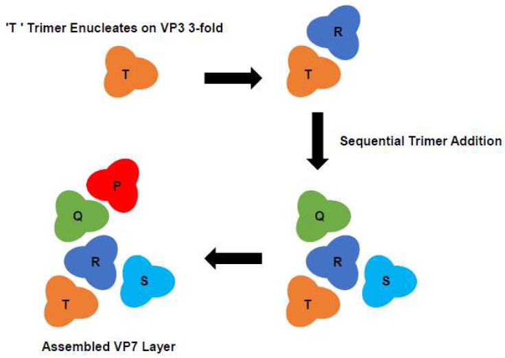
Figure 5.
Diagram of Proposed VP7 Assembly Pathway. VP7 trimers are labelled P, Q, R, S and T. In the proposed model of core assembly, multiple sheets of VP7 form at different nucleation sites. A process which is initiated by a single VP7 trimer (‘T’) occupying the ‘preferred’ site for assembly on the VP3. The ‘T’ trimer becomes the most tightly attached trimer, which is subsequently followed by the progressively weaker attachment of four more VP7 trimers (R-Q-S-P) which ‘fill the gaps’ (Adapted from [27]).

