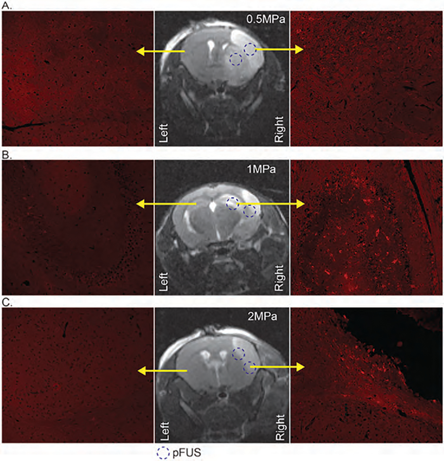
Figure 8.

MRI images (middle column) to indicate the stroke area of mice and dotted circle to delineate the 2 pFUS application points. The right column with fluorescent microscopy images to show DiI-labeled (red) exosomes from the right hemisphere of the mice with 0.5 MPa (A), 1 MPa (B), and 2 MPa (C) pFUS application; left columns with fluorescent microscopy images to show the contralateral side of the brain without stroke and pFUS application.
